
{{product.productLabel}} {{product.model}}
{{#if product.featureValues}}{{product.productPrice.formattedPrice}} {{#if product.productPrice.priceType === "PRICE_RANGE" }} - {{product.productPrice.formattedPriceMax}} {{/if}}
{{#each product.specData:i}}
{{name}}: {{value}}
{{#i!=(product.specData.length-1)}}
{{/end}}
{{/each}}
{{{product.idpText}}}

Ansys Polyflow is a finite-element based CFD software used to reduce the cost of polymer, glass, metals and cement processing. Accurately Assess Viscoelastic Fluids Ansys Polyflow accelerates design time while shrinking ...
ANSYS
... Design Reverse Engineering 3D Printing Motion Dynamics STL Prep for 3D Printing Model Prep for Simulation Sheet Metal Modeling for CAE Additive Manufacturing Ansys SpaceClaim ...
ANSYS
Ansys Discovery features the first simulation-driven design tool combining instant physics simulation, high-fidelity simulation and interactive geometry modeling in a single easy-to-use experience. Ansys Discovery Reveals Critical ...
ANSYS

... powerful visualisation & point cloud navigation plus a complete tool set for High-Definition Surveying (HDS™) applications in engineering, construction and asset management. Cyclone SURVEY provides unmatched office ...
Leica Geosystems

... tables. TopSolid’Progress helps you prepare your engineering projects with, for example the option of conversion into sheet metal, the identification of folds and loss management. As a machining software, ...

... object-oriented design and engineering of control applications. IEC 61131-3 engineering Control Builder is a powerful tool for creating control solutions and reusable control libraries for the AC ...
ABB Control Systems
... MX Sheet This software enables Microsoft's Excel package to monitor, log, collect alarm information and change configurations for the PLC. Other engineering softwares Lineup of various ...
MITSUBISHI Automation

The central software tool is the IndraWorks engineering framework for efficient planning, programming, commissioning and diagnosis of different applications via the entire product lifecycle of a machine. ...
Bosch Rexroth - Electric Drives and Controls

EPLAN Fluid is your engineering tool especially for designing and automatically documenting schematics for fluid power systems including hydraulics, pneumatics, cooling and lubrication. The software supports ...
EPLAN Software & Service

... , experts show that data consistency, data quality and data depth play a decisive role for modern companies even beyond engineering. Request your free PDF now!
EPLAN Software & Service

The EPLAN Platform offers software for a wide variety of engineering disciplines from a single source – and more than just traditional ECAD software. From preplanning to electrical engineering ...
EPLAN Software & Service

... automation services, from digital planning to integrated engineering and transparent operation. With TIA Portal you gain valuable competitive advantages! TIA Portal – more than an engineering framework More ...
Siemens Automation and Engineering
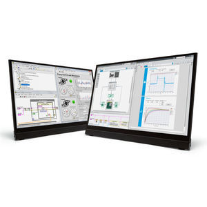
LabVIEW is systems engineering software for applications that require test, measurement, and control with rapid access to hardware and data insights. The LabVIEW programming environment simplifies ...
NATIONAL INSTRUMENTS

... as in the industry-leading DraftSight® desktop software — with added collaboration and data management functionality on the cloud-based 3DEXPERIENCE Platform. Trusted by Many DraftSight CAD software ...
SOLIDWORKS Europe

This comprehensive software suite includes various programming software for PLC, motion control, and GOT. IQ Works is an integrated software suite consisting of GX Works3, MT Works2, ...
MITSUBISHI ELECTRIC AUTOMATION

Autodesk Civil 3D: Comprehensive detailed design and documentation software for civil infrastructure Autodesk Civil 3D® design software empowers civil engineers to meet complex infrastructure challenges ...
AUTODESK
DIGSI 5 is the versatile engineering tool for parameterization, commissioning and operating all SIPROTEC 5 devices. Its innovative user interface includes context-sensitive user instructions. Simple connection to the ...
... Publish 3D Data with Annotations and Views SOLIDWORKS MBD helps you communicate directly in 3D. If you like 3D PDF, the software can customize the templates, control accuracies and PDF sizes, publish BOM tables and ...
SOLIDWORKS
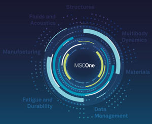
MSCOne is a definitive collection of the most advanced simulation software. Now designers and engineers can flexibly access all the CAE software they might need with a low barrier to entry thanks to our ...
MSC SOFTWARE - HEXAGON MANUFACTURING INTELLIGENCE
... including MSCADS and IPOPT. The fatigue capability in MSC Nastran has been developed jointly by nCode International Ltd. and MSC Software.
MSC SOFTWARE - HEXAGON MANUFACTURING INTELLIGENCE

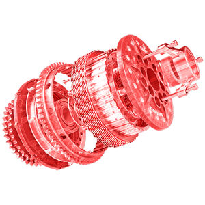
... Simulate "Real World" Physics As the worlds most famous and widely used Multibody Dynamics (MBD) software, Adams improves engineering efficiency and reduces product development costs by enabling ...
MSC SOFTWARE - HEXAGON MANUFACTURING INTELLIGENCE

... alter your software application and can be set up within minutes. With Webspace, you can reduce costs and improve time to action—driving sustainable advantages across all levels of your business, including management, ...
General Electric
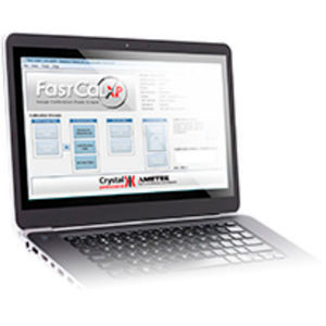
FastCalXP software allows you to complete a 10 point up and down calibration in less than 3 minutes including printing out a calibration certificate. FastCalXP frees you from manually recording and interpolating gauge ...
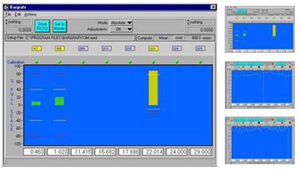
... analog output voltage and scales it into linear engineering units (either English or metric) using polynomial interpolation (to 5th degree) Benefits Ease of set-up and use with industry standard software Accuracies ...
... sophisticated image processing and defect detection applications, consider TrueTest™ Automated Visual Inspection software. ProMetric Software Provides: Complete luminance and color measurement data ProMetric ...
Radiant Vision Systems

... assemblies and surfaces, multiple tests may need to be performed to inspect products for a range of evaluation criteria. TrueTest™ Software equips ProMetric® Imaging Colorimeters and Photometers to be used for in-line ...
Radiant Vision Systems
... may strongly impact product usability. A member of the Radiant Vision Systems ProMetric Software family, the PM-KB system combines application-specific software and a ProMetric® Imaging Colorimeter ...
Radiant Vision Systems
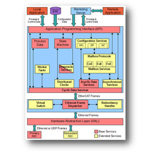
... with a view to high performance, low resource commitment and good scalability • Core components of the stack software are independent of operating system and CPU architecture • EtherCAT Master ...
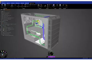
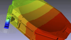
... element modeling software especially suited for solid element modeling. A variety of very well laid out processes are included and will accelerate your work significantly. SimLab allows you to quickly and accurately ...
ALTAIR
... CAE simulation tasks, automating the execution of reoccurring procedures and generating an easy-to-access repository of engineering knowledge. Collaboration Tools Every installation of HyperWorks comes out of the box ...
ALTAIR
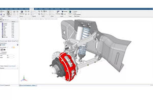
Parametric modeling interface to model and visualize high-fidelity Multi-body systems.Altair® MotionView® is a user-friendly and intuitive multibody systems modeling environment. Its built-in parametric modeling capability and open architecture ...
ALTAIR
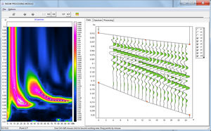
... interpretation of seismic tomography data on refracted and reflected waves (land, cross-borehole and water variants). The software includes the following modules: 1. MASW/ReMi – surface waves data processing and interpretation, ...
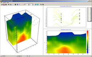
... which appear as variations in seismic velocities. Cross-well seismic tomography has received the greatest popularity in engineering geophysics. This direction is used for a detailed study of the structure of the rock ...

... most significant features that Osiris has to offer: Runs on portable Mercury tablet, permanent Atlas unit and as a software Supports versions v1, v2c and v3 of the SNMP protocol Automatic communication ...

Software for Low Voltage and High Voltage electrical installations calculation elec calc™ is a software package that enables the calculation of low voltage and high voltage electrical installations ...
INVENTEO is a complete metallurgical accounting software solution compliant with the P754 AMIRA code. It performs: •Automatic plant data acquisition and processing •Data reconciliation based on material balance ...
Please specify:
Help us improve:
remaining