- Hydraulics - Pneumatics
- Compressor
- Piston compressor
- Burckhardt Compression AG
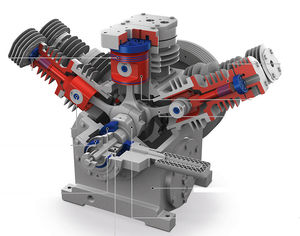
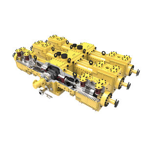
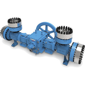
Piston compressor Laby®gaselectrically-poweredstationary


Add to favorites
Compare this product
Characteristics
- Technology
- piston
- Type
- gas
- Power source
- electrically-powered
- Portability
- stationary
- Lubrication
- oil-free
- Application domain
- industrial, for the petrochemical industry
- Applications
- process, for the gas industry
- Pressure
1.17 bar, 1.2 bar, 1.5 bar, 6.8 bar
(16.97 psi, 17.4 psi, 21.76 psi, 98.63 psi)- Flow
725 m³/h, 2,620 m³/h, 3,015 m³/h, 5,340 m³/h
(25,603.13 ft³/h, 92,524.43 ft³/h, 106,473.72 ft³/h, 188,580.32 ft³/h)- Power
Min.: 115 kW
(156.36 hp)Max.: 5,360 kW
(7,287.57 hp)
Description
Since Burckhardt Compression first introduced the Laby® Compressor in 1935 we have been able to increase our application know-how. In close cooperation with our customers we have transferred this know-how into a second to none compressor solution with outstanding performance. Originally designed for the safe compression of ammonia, continuous improvements and further developments have made the Laby® today one of the most reliable compressor solutions for numerous applications handling complex gases:
– bone-dry gases
– humid gases
– cryogenic gases
– dirty, dust-laden, contaminated gases in fouling services
– clean gases where no pollution of the gas is allowed
– reactive, explosive, corrosive or toxic gases
All major industrial gas suppliers, global players in the polyolefin production, renowned process licensees, international partners for gas liquefaction systems and many producers of chemicals trust Burckhardt Compression and depend on the unsurpassed reliability of Laby® Compressors. Thousands of installations underscore this long success story.
Labyrinth Sealing – Contactless, Oil-Free Compression
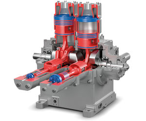
The unique technology is applied between the piston and the cylinder wall and between the piston rod gland and the piston rod. The labyrinth sealing effect is created by numerous tiny throttling points. At each of these throttling points, pressure energy is transformed into kinetic energy as a result of the flow restriction. The process continues at each throttling point/volume chamber combination along the piston and piston rod gland until the required reduction in pressure is attained. A small clearance volume is maintained between the adjoining surfaces.
Catalogs
Exhibitions
Meet this supplier at the following exhibition(s):

Other Burckhardt Compression AG products
COMPRESSOR TECHNOLOGIES
Related Searches
- Compressor stage
- Air and dry gas compressor
- Positive-displacement compressor
- Fixed compressor
- Industrial compressor
- Electrically-powered compressor
- Reciprocating compressor
- Oil-injected compressor
- Dry compressor
- Compact compressor
- Cooled compressor
- Tank-mounted compressor
- Gas compressor
- Air-cooled compressor
- High-pressure compressor
- Rugged compressor
- Single-stage compressor
- Water-cooled compressor
- Compressor with combustion engine
- Diesel-powered compressor
*Prices are pre-tax. They exclude delivery charges and customs duties and do not include additional charges for installation or activation options. Prices are indicative only and may vary by country, with changes to the cost of raw materials and exchange rates.


