- Products
- Switch module
- CGS Computer Gesteuerte Systeme GmbH
CAN Bus switch module
Add to favorites
Compare this product
fo_shop_gate_exact_title
Characteristics
- Options
- CAN Bus
Description
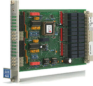
The CL22 is designed to switch CAN-H and CAN-L signals. The logic levels are additionally shown on a LED display. If this should interfere with the CAN signal, the display can be deactivated. It is possible for error simulation purposes to connect each channel with GND or Ubatt +. This function, for instance, can be used to simulate a broken wire. The sockets on the front panel are connected directly with the inputs of the channels. This allows it, for example, to supply the CAN signals directly from a laptop with Vector CANoe for diagnostic purposes.
Catalogs
No catalogs are available for this product.
See all of CGS Computer Gesteuerte Systeme GmbH‘s catalogsOther CGS Computer Gesteuerte Systeme GmbH products
Electronic Boards
*Prices are pre-tax. They exclude delivery charges and customs duties and do not include additional charges for installation or activation options. Prices are indicative only and may vary by country, with changes to the cost of raw materials and exchange rates.


