
Serial interface expansion card Unipi 1.1Raspberry Pi

Add to favorites
Compare this product
Characteristics
- Interface
- serial
- Other characteristics
- Raspberry Pi
Description
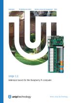
Unipi 1.1 is an extension board for the Raspberry Pi computer which allows it to function as a programmable logic controller for monitoring, control and regulation of automation systems. The board features a universal I/O architecture with digital inputs, a set of relays, analogue I/Os and broad connectivity thanks to 1-Wire bus, I2C and UART ports.
Package contents
Unipi 1.1 board
quick start guide
26 pin (2×13) flat cable to connect Unipi 1.1 to Raspberry Pi
3× metal spacer 2M5 (20mm)
3× screw 2M5
3× nut 2M5
Basic Unipi 1.1 features
8× changeover relay (250 V AC/10A; 30 V DC/10 A)
12 + 2× galvanically isolated digital input (5-24 V DC, min. pulse length 5 ms)
2× analog input (0 - 10 V)
1× analog output (0 - 10 V)
1× 1-Wire bus
1× I2C port
1× UART port
RTC module (battery not included)
Inputs & outputs
Digital inputs (DI) are designed to read binary logic states represented by direct voltage levels. That makes them suitable for reading data from various binary sensors and devices such as switches (on/off), motion sensors (movement detected/not detected), liquid level sensors (full tank/empty tank) etc.
Note: By default the digital inputs 13 and 14 are inaccessible. For their use please visit this tutorial.
Relay outputs (RO) are primarily used for switching two-state devices with higher current draw such as lightbulbs, thermoelectric valve drives, water heaters, pumps etc.
Analog inputs (AI) serve for measuring 0-10V DC voltage from various analog sensors such as thermometers, pressure meters, tensometers etc.
Catalogs
Unipi 1.1
14 Pages
Related Searches
- Industrial gateway
- Ethernet gateway
- Programmable logic controller
- Serial gateway
- DIN rail gateway
- IoT gateway
- RS-485 gateway
- Communication interface card
- RS485 programmable controller
- Compact gateway
- Compact programmable controller
- Cabinet PLC
- DIN rail programmable logic controller
- Digital input programmable controller
- Digital outputs programmable controller
- Analog outputs programmable controller
- Serial interface expansion card
- Linux gateway
- Relay expansion module
- Programmable gateway
*Prices are pre-tax. They exclude delivery charges and customs duties and do not include additional charges for installation or activation options. Prices are indicative only and may vary by country, with changes to the cost of raw materials and exchange rates.