
{{product.productLabel}} {{product.model}}
{{#if product.featureValues}}{{product.productPrice.formattedPrice}} {{#if product.productPrice.priceType === "PRICE_RANGE" }} - {{product.productPrice.formattedPriceMax}} {{/if}}
{{#each product.specData:i}}
{{name}}: {{value}}
{{#i!=(product.specData.length-1)}}
{{/end}}
{{/each}}
{{{product.idpText}}}
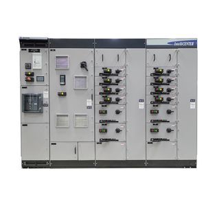
... Our CENTERLINE® 2500 IEC low voltage motor control centers (MCCs) pass rigorous certification processes to meet application requirements around the world. Designed with a smaller footprint, the MCCs meet ...
Allen-Bradley

... The motor control center controls and protects the electric motors installed in plants. ...

... Name : Low-Voltage Motor Control Center Features ‧Personnel safety and ease of maintenance ‧Shock and vibration resistance ‧Easy mounting of channel bases and interconnection of enclosures ‧Easy ...

... Product Item : MOTOR CONTROLL CENTER Specification : ‧ SPECIFICATION APPLIED TO WHAT CUSTOMER’S INQUIRY. A) 440V 55kW below, you can choose draw-out type, you can draw out every single unit. B) You do not have ...

... Motor control centers CL21 The motor control centers control and protect the electric motors installed ...

... distribution board, equipped with withdrawable slide-boxes and compartments, represent the optimal solution in electrical distribution, automation, motors control and protection, for all the industrial ...
the best suppliers