
{{product.productLabel}} {{product.model}}
{{#if product.featureValues}}{{product.productPrice.formattedPrice}} {{#if product.productPrice.priceType === "PRICE_RANGE" }} - {{product.productPrice.formattedPriceMax}} {{/if}}
{{#each product.specData:i}}
{{name}}: {{value}}
{{#i!=(product.specData.length-1)}}
{{/end}}
{{/each}}
{{{product.idpText}}}
... >
Other resources / tools
- Open area calculation, sheet weight and unfolded sheet size calculators (tools for design and specification).
- Pattern catalogue
RMIG
... and low-volume sheet metal fabrication. We handle laser cutting, turret punching, bending, and welding for aluminum, steels and stainless steels to produce high-quality sheet metal components. We accommodate ...

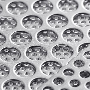
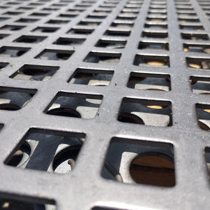
... The holes are round (R), square (C), hexagonal (H), oblong (LR), rectangular (LC) or diamond-shaped (CD). The arrangement of the perforations is defined by the letters T-U-Z-M according to the arrangement of the holes in relation to each other. ...
GANTOIS INDUSTRIES
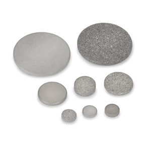
... Porous metal discs, designed with precision by Mott, can be tailored for an extensive range of applications and specifications. These porous metal discs can be encapsulated in diverse metallic and non-metallic ...
Mott
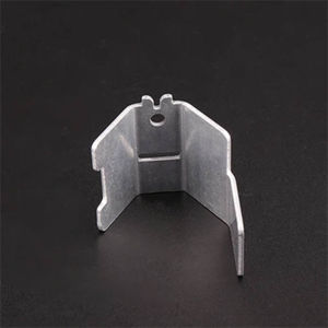
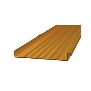
... This metal bracket is precisely formed from high-strength stainless steel and features a clean, brushed or zinc-plated surface for enhanced corrosion resistance. Designed with tight tolerances, it ensures ...
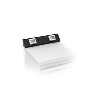
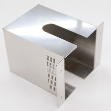
The system LMD-B 100 features visible Post Cap profiles in linear arrangement. If necessary, partitions can be fastened to Post Cap profiles to individually divide your rooms. The striking profiles can be used for technical installations and can easily ...
Lindner Group
Impact and abrasion-resistant, they can also be made from special high-strength materials up to 500 HB. Available flat for vibrating screens (with or without tensioning hooks) or rolled for trommels.
Sovatec srl
... hot rolled mild steel sheets, pre-galvanized sheets, aluminum sheets, stainless steel 304, Stainless steel ...
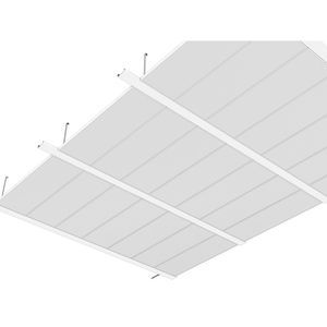
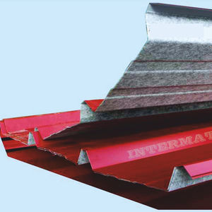
... does not require a solid substructure for support. Applications: Panel Systems, Roof Systems, Standing Seam Roof Systems Coverage Width: 12", 16" Minimum Slope: ½:12 Panel Attachment: Concealed Fastening System, ...
Star Building Systems
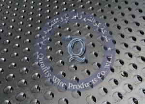
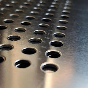
... Open Area, Strength) Quality Perforated Metal Quantity : Number of full sheets Material : Type of Material desired such as Carbon Steel, Stainless Steel, Aluminium etc Thickness : For steel or stainless ...
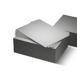
... We produce metal sheets and strips in a wide range of alloys and formats thanks to five automated transversal cutting lines for the most diverse sectors and applications, designing and constructing – also in a short time ...