- Machine-tools
- Machine Tool Accessory
- Vertical tool turret
- Duplomatic Automation
- Products
- Catalogs
- News & Trends
- Exhibitions
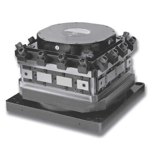
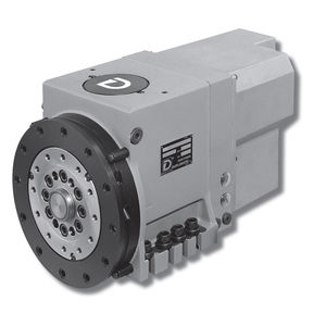
Vertical tool turret TRM-S Seriesvertical-axishydraulicservo-driven

Add to favorites
Compare this product
Characteristics
- Type
- vertical
- Orientation
- vertical-axis
- Other characteristics
- hydraulic, servo-driven
Description
TRM-S series 20
VERTICAL AXIS SERVOMOTOR TURRETS
TOOLHOLDERS CLAMPING DIN 69881-1
TRM-S / series 20
COOLANT CIRCUIT
"4" POSITIONS
Each turret has two inlets for the coolant, respectively R and R1, fitted on the base plate.
The coolant passes from the base to the turret housing through the two valves V and V1.
On the tool post the coolant outles are:
• External coolat through the outlet holes on the top of tool post R U ; R1 U1.
• Internal coolat directly on the tool hoolder through the valves E.
The working of the valve "E" is sketched on the fig. 3 and 4.
Fig. 3 without toolholders (closed valve)
Fig. 4 with toolholders (open valve)
By changing the position of the intercepting valves F1, F2,
F3, F4 is possible to variate the coolant outlet obtaining the follow configurations :
R E2 R1 E3 R E1 R1 E2
The turrets are normally delivered with all the F* valves fitted inside, that is internal coolant circuit all closed.
"6" POSITIONS
The TRM-S-6 position turrets have one only inlet for the coolant (R) fitted on the base plate.
The (R1) position is plugged and must not be used.
The coolant pass through the base to the turret housing through the valve V1.
On the tool post the coolant outles are:
• External coolat through the outlet holes on the top of tool post R U.
• Internal coolat directly on the tool hoolder through the valve E.
Catalogs
TRM-S
18 Pages
Related Searches
- Chuck
- Milling chuck
- Machining tool holder
- Collet tool holder
- Milling tool holder
- Intermittent index unit
- Tapping holder
- Machine tool rotary indexing table
- Horizontal rotary indexing table
- VDI chuck
- VDI tool holder
- Tool turret
- Disc tool turret
- BMT tool holder
- CAPTO chuck
- Machining center tool holder
- Hydraulic tool turret
- CAPTO tool holder
- Direct-drive rotary indexing table
- Hydraulic rotary indexing table
*Prices are pre-tax. They exclude delivery charges and customs duties and do not include additional charges for installation or activation options. Prices are indicative only and may vary by country, with changes to the cost of raw materials and exchange rates.


