
{{product.productLabel}} {{product.model}}
{{#if product.featureValues}}{{product.productPrice.formattedPrice}} {{#if product.productPrice.priceType === "PRICE_RANGE" }} - {{product.productPrice.formattedPriceMax}} {{/if}}
{{#each product.specData:i}}
{{name}}: {{value}}
{{#i!=(product.specData.length-1)}}
{{/end}}
{{/each}}
{{{product.idpText}}}
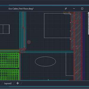
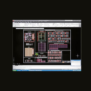
... AutoCAD on the web (included) View, annotate, and share 3D DWG files and edit 2D drawings with a simple user interface on any computer. Just sign in and get to work—no software installation is required. Use AutoCAD ...

... for datasheets, preliminary layout drawings, etc. Collaboration Assists construction contractors by helping to create construction work packages, which can be a combination of 3D plant views and text/ schematics. Versatile Maintenance ...
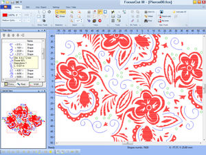
... Typographic composition software, drawing for engraving, marking and 2 and 2.5 dimensional cutting, hatch fill or island fill carving, tangential entry and exit... There are many functions as : special effects, ...

... Paint, sketch, and animate in the powerful, go-everywhere drawing app with thousands of brushes and pro features — completely free. Create with thousands of brushes. Make your masterpiece with exclusive brush packs you can’t get ...
elec calc™ EP is dedicated to public Lightning - only for France
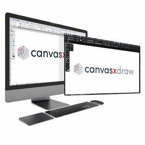
... digital drawing software that does everything you need One powerful app for all your vector and raster graphics. Simple enough for beginners. Rich enough for pros. Priced for everyone. feature rich - all the tools ...
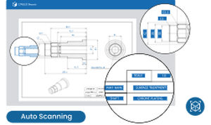
... Streamline manufacturing insights with batch uploads of all 2D drawings into one central system Extract all data from drawings, including dimensions, texts, and shapes. Make even handwritten drawings ...
... fabrication relevant data from the drawings. It provides the basis for all following calculations. Thanks to an integrative database all details regarding the pipeline elements are known. Hence the system can use the drawings ...

... of additional training on the software. Some features: - Windows based software. - Parametrical drawing of 2D profiles. - No more calculating while drawing profiles with ...
... 1977 we have developed software with the aim of providing our Customers with products that are complete and fully-developed, yet at the same time functional and easy to use. Over the years we have designed and produced many software ...

... Filters are available to organise work according to preferences Possible to filter by device, color, wire size, etc. Drawing can be explored with finger or mouse to have a clear view on the work to do ...
... compatible, efficient, and agile drafting solution you will find. It can edit drawings from eight of the most popular CAD formats, as well as being able to create drawings from solids. KeyCreator Pro and Prime versions ...
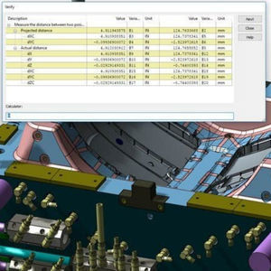
... precise hidden line information for 2D drawing sheets by analyzing models in specific views and determining if lines are visible, occluded or hidden. Visibility Calculate visible properties for optimal drawing ...
... The VenturisIT GmbH product - TRICAD MS® Module, is basically a 3D CAD software and aids in creating scalable schematics. The two prime functions 'automatic pipe recognition' and 'rubber band' helps in easy designing ...
... Radraft is a drafting solution manufactured by Radan for all 2D design & drawing needs. It is equipped with an easy-to-use graphical interface for cost-efficiency and reliability. This tool provides an extensive drafting solution for ...
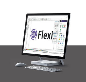
... OKKURA has partnered with SAI and is a reseller of the Flexi software which integrates directly with the OKKURA controller. Flexi allows you to draw or convert drawings into cut-ready artwork. • 4 Packages Available • ...
... The software, designed by Schnell Home engineers, makes the production and installation of prefabricated sandwich panels much easier. The software works with AutoCAD and: - calculates the m² of insulating panels, ...
the best suppliers