


- Detection - Measurement
- Optical and Acoustic Measurements
- Class A pyranometer
- SEVEN Sensor Solutions
Class A pyranometer 3S-ISRS-485serialModbus RTU

Add to favorites
Compare this product
Characteristics
- IEC 61724-1
- class A
- Output signal
- RS-485, serial, Modbus RTU
- Options
- for solar energy test applications, digital
Description
Overview
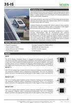
The 3S-IS irradiance sensor provides temperature‑compensated irradiance measurements for PV plants and transmits data via Modbus RTU over RS485. Supplied with mounting bracket and 3 m UV‑resistant LIYYC11Y cable, the aluminium UV‑protected housing is available in IP54 (standard) with IP65/IP68 options for harsher environments. Designed for plug‑and‑play integration with PLC, SCADA and data loggers.
How the 3S-IS Sensor Works
Why Choose the 3S-IS Irradiance Sensor?
Technical specifications
Item Code: 3S-IS, 3S-IS-1, 3S-IS-2, 3S-IS-2T, 3S-IS-3, 3S-IS-4, 3S-IS-5
Reference Cell: Monocrystalline silicon (31 mm × 31 mm)
Irradiance Range: 0–1600 W/m²
Uncertainty: ≤1% (IEC 61724-1 Class A)
Resolution: 0.1 W/m²
Response Time: 1 s (500 ms optional)
Drift: <0.3% / year
Field of View: >160°
Tilt‑Azimuth Angle: 0°–0°, ≤1°
Output Rate: 1 Hz
Data Output: RS485 up to 38400 Baud
Protocol: Modbus RTU
Power Supply: 12–30 V DC
Power Consumption: 30 mA max @24 VDC
Cable: 3 m LIYYC11Y PUR, UV and weather resistant
Galvanic Isolation: 1000 V between power and RS485 bus
Cell Temp. Sensor: PT1000 Class A (EN 60751)
Operating Temp.: −40 °C to +85 °C
Operating Humidity: 0–100%
Dimensions: 140 × 110 × 42 mm (W × L × H)
Weight: 0.3 kg
IP Rating: IP54 (IP65, IP68 options)
Housing: Aluminium
Standards: IEC 61724-1:2021, IEC 60904 series
Calibration: Each unit calibrated on Class AAA sun simulator per IEC 60904-2 / IEC 60904-4 using reference cell calibrated by ISFH; outdoor verification vs Fraunhofer ISE reference cell.
Available models (summary)
3S-IS / RS485 Modbus RTU / ≤1% / No external sensor inputs
3S-IS-1 / RS485 Modbus RTU / ≤1% / Ambient OR Module Temperature sensor
3S-IS-2 / RS485 Modbus RTU / ≤1% / Ambient OR Module Temperature; Wind Speed sensor
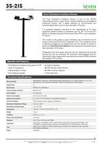
3S-IS-2T / RS485 Modbus RTU / ≤1% / Ambient AND Module Temperature sensors
3S-IS-3 / RS485 Modbus RTU / ≤1% / Ambient, Module Temperature and Wind Speed
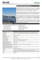
3S-IS-4 / RS485 Modbus RTU / ≤1% / Ambient, Module, Wind Speed; Wind Direction OR Relative Humidity
3S-IS-5 / RS485 Modbus RTU / ≤1% / Module Temp, Wind Speed, Wind Direction, Relative Humidity and Ambient Temp
Modbus specification
Calibration and tests
Each sensor is calibrated on a Class AAA solar simulator according to IEC 60904-2 and IEC 60904-4 using an ISFH‑calibrated reference cell. Units are additionally verified outdoors against a Fraunhofer ISE calibrated reference cell.
Applications
Performance monitoring and energy yield assessment of PV plants, integration with PLC/SCADA and data loggers, meteorological stations and PV test sites.
Components
The 3S-IS irradiance sensor provides temperature‑compensated irradiance measurements for PV plants and transmits data via Modbus RTU over RS485. Supplied with mounting bracket and 3 m UV‑resistant LIYYC11Y cable, the aluminium UV‑protected housing is available in IP54 (standard) with IP65/IP68 options for harsher environments. Designed for plug‑and‑play integration with PLC, SCADA and data loggers.
How the 3S-IS Sensor Works
- A monocrystalline reference cell generates a short‑circuit current proportional to incident irradiance.
- A precision shunt resistor converts the current into a measurable voltage signal.
- A PT1000 temperature sensor mounted at the back of the cell compensates for thermal effects.
- An electronic board processes signals and calculates temperature‑compensated irradiance values in W/m².
- Data are transmitted to receivers via RS485 using the Modbus RTU protocol.
Why Choose the 3S-IS Irradiance Sensor?
- Measurement class: IEC 61724-1 Class A compliance with uncertainty ≤1%, calibrated per IEC 60904-2.
- Fast response: Standard 1 s response time (optionally 500 ms on request) for near real‑time monitoring.
- Field‑ready: UV‑protected aluminium housing with IP54 standard (IP65/IP68 options) and operating range −40 °C to +85 °C.
- Easy integration: Plug‑and‑run design; Modbus RTU over RS485 for direct connection to PLC, SCADA and data loggers.
- Expandable: Model options allow connection of external sensors (ambient/module temperature, wind, humidity, wind direction) to act as a monitoring hub.
Technical specifications
Item Code: 3S-IS, 3S-IS-1, 3S-IS-2, 3S-IS-2T, 3S-IS-3, 3S-IS-4, 3S-IS-5
Reference Cell: Monocrystalline silicon (31 mm × 31 mm)
Irradiance Range: 0–1600 W/m²
Uncertainty: ≤1% (IEC 61724-1 Class A)
Resolution: 0.1 W/m²
Response Time: 1 s (500 ms optional)
Drift: <0.3% / year
Field of View: >160°
Tilt‑Azimuth Angle: 0°–0°, ≤1°
Output Rate: 1 Hz
Data Output: RS485 up to 38400 Baud
Protocol: Modbus RTU
Power Supply: 12–30 V DC
Power Consumption: 30 mA max @24 VDC
Cable: 3 m LIYYC11Y PUR, UV and weather resistant
Galvanic Isolation: 1000 V between power and RS485 bus
Cell Temp. Sensor: PT1000 Class A (EN 60751)
Operating Temp.: −40 °C to +85 °C
Operating Humidity: 0–100%
Dimensions: 140 × 110 × 42 mm (W × L × H)
Weight: 0.3 kg
IP Rating: IP54 (IP65, IP68 options)
Housing: Aluminium
Standards: IEC 61724-1:2021, IEC 60904 series
Calibration: Each unit calibrated on Class AAA sun simulator per IEC 60904-2 / IEC 60904-4 using reference cell calibrated by ISFH; outdoor verification vs Fraunhofer ISE reference cell.
Available models (summary)
3S-IS / RS485 Modbus RTU / ≤1% / No external sensor inputs
3S-IS-1 / RS485 Modbus RTU / ≤1% / Ambient OR Module Temperature sensor
3S-IS-2 / RS485 Modbus RTU / ≤1% / Ambient OR Module Temperature; Wind Speed sensor
3S-IS-2T / RS485 Modbus RTU / ≤1% / Ambient AND Module Temperature sensors
3S-IS-3 / RS485 Modbus RTU / ≤1% / Ambient, Module Temperature and Wind Speed
3S-IS-4 / RS485 Modbus RTU / ≤1% / Ambient, Module, Wind Speed; Wind Direction OR Relative Humidity
3S-IS-5 / RS485 Modbus RTU / ≤1% / Module Temp, Wind Speed, Wind Direction, Relative Humidity and Ambient Temp
Modbus specification
- Baud rates: 1200, 2400, 9600, 19200, 38400
- Parity: None, Even, Odd
- Stop bits: 1 or 2 (2 only if Parity = None)
- Default configuration: 9600, 8N1, address 1
Calibration and tests
Each sensor is calibrated on a Class AAA solar simulator according to IEC 60904-2 and IEC 60904-4 using an ISFH‑calibrated reference cell. Units are additionally verified outdoors against a Fraunhofer ISE calibrated reference cell.
Applications
Performance monitoring and energy yield assessment of PV plants, integration with PLC/SCADA and data loggers, meteorological stations and PV test sites.
Components
- UV‑resistant aluminium sensor housing
- Laminated monocrystalline PV reference cell (EVA/Tedlar)
- Electronic board with microcontroller for signal conditioning and Modbus RTU communication
Catalogs
Exhibitions
Meet this supplier at the following exhibition(s):


Other SEVEN Sensor Solutions products
Irradiance Sensors


Related Searches
- Pyranometer
- ISO 9060 pyranometer
- Spectrally flat pyranometer
- Digital pyranometer
- Modbus pyranometer
- Solar reference cell
- Photovoltaic detection module
- Analog pyranometer
- Class A pyranometer
- RS-485 pyranometer
- Albedometer
- Digital solar radiation sensor
- Solar radiation sensor with temperature sensor
- Photovoltaic system albedometer
- Spectrally flat albedometer
- HgCdTe photovoltaic detection module
- RS485 solar reference cell
- Voltage output pyranometer
- Thermopile pyranometer
- Modbus RTU pyranometer
*Prices are pre-tax. They exclude delivery charges and customs duties and do not include additional charges for installation or activation options. Prices are indicative only and may vary by country, with changes to the cost of raw materials and exchange rates.