
{{product.productLabel}} {{product.model}}
{{#if product.featureValues}}{{product.productPrice.formattedPrice}} {{#if product.productPrice.priceType === "PRICE_RANGE" }} - {{product.productPrice.formattedPriceMax}} {{/if}}
{{#each product.specData:i}}
{{name}}: {{value}}
{{#i!=(product.specData.length-1)}}
{{/end}}
{{/each}}
{{{product.idpText}}}

... bevels, saddlebacks, etc. RX-Universe interfaces with latest lens manufacturing machines & software from Satisloh and other manufacturers. A lab management software that grows with you The systems gives labs great ...

... A further evolution for exclusive design. Optimized high tech allows you to have much more accurate data. Able to analyze real information of each visual measurement of the user, creating a much more accurate mathematical calculation for each lens. Benefits 100% ...
... systems (GIS) optimized. CAD CAD-based prototyping. Alignment Automated alignment and drift control. Patterning sequences Plan patterning sequences on your desktop PC using Thermo Scientific NanoArchitect ...
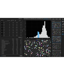
... Scientific Phenom ParticleMetric Software allows you to gather morphology and particle size data for numerous sub-micron particle applications with any Phenom Desktop SEM. The fully automated measurements of ParticleMetric Software ...

... What is QUINDOS? QUINDOS is the leading modular metrology software for special geometries used for powertrains in aerospace, energy, automotive, and engineering. Powerful enough to handle the most complex and demanding metrology projects, ...

... simple Highly flexible, REcreate stands apart from traditional reverse engineering software by incorporating a CAD system that can create 2D drawings as well as CAD models. REcreate fits into any existing ...

... Geomagic Design X is purpose-built for converting 3D scan data into high-quality feature-based CAD models. It does what no other software can with its combination of automatic and guided solid model extraction, incredibly ...

... 2D X-ray Inspection Software Large and powerful image processing software to program automatic test cycles. Manual, as well as fully automated X-ray inspection, can be done easy and self-explanatory. Fast and easy ...
... Open and flexible CAD software Communication with most of the formats on the market Step, IGES, DXF/DWG, Solidworks, PTC, Catia... Point cloud import (xyz, pts, ply) from 3D scanners Direct editing tools ...
TOPSOLID SAS

... TopSolid’Wood: a customized solution that adapts to your needs TopSolid'Wood is the only integrated CAD/CAM software package specially developed to meet the needs of the wood industry. Unlimited creativity: ...
TOPSOLID SAS
... CADCAM software that offers a broad selection of manual functions and centralize your data to make considerable time savings in the industrialization of your projects. This 3D design software is also a manufacturing ...
TOPSOLID SAS

... ABC: simple engraving software for personalization and small signage CAD AND DRIVING SOFTWARE ABC software is the easiest engraving software for Gravotech laser and ...
... TYPE3-CAA : DESIGN, VECTORIZE, INTEGRATE TEXTS, LOGOS, SYMBOLS directly in the CATIA® PLM process CAD/CAM SOFTWARE TYPE3-CAA is the only add-on available in CATIA ® environment for text creation and mapping. • Create ...
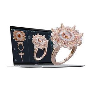
... 3DESIGN : 3D JEWELRY CAD SOFTWARE
Cutting edge 3D
software for jewelry design that will keep your business ahead.
Key features:
- Intuitive tools reflecting
... Eastman’s operating control software, CutPRO, is a dynamic, all-inclusive platform that makes it effortless to operate Eastman’s automated cutting system. Eastman’s operating control software is a dynamic, all-inclusive ...
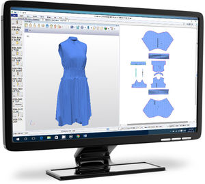
... Eastman’s patternPRO design and nesting software is a comprehensive set of tools to help you design pattern pieces from the start with the program’s drafting and editing tools, or even edit and finalize your existing digital patterns, ...
... CodeSoft software This enterprise-level label design software allows users to design and print custom labels for product identification and tracking. CodeSoft software is the professional solution for ...
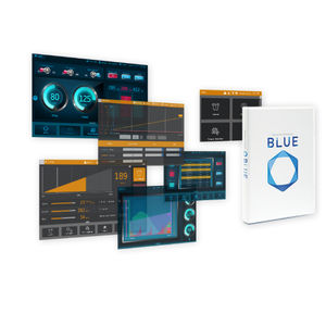
... Versatile Software BLUE Versatile Software Revolution new software, BLUE will offer an alternative experience in hardware design. Anyone can easily create and change dynamic screens that allow for ...

... Roland R-Wear Studio software comes with all of the necessary tools to design beautiful custom apparel and gifts. The software makes it easy to boost profits by personalising everything from t-shirts and handbags to wine ...
ROLAND
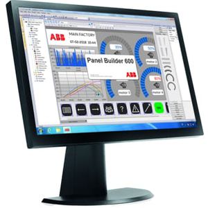
... CP600-eCo - Software PB610 Panel Builder 600 - engineering tool for easy design of tailor-made graphical user interfaces for the entire CP600 control panels platform Tailor-made human machine interface (HMI) For the efficient design ...
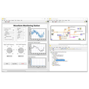
... tools. To ensure compatibility with other engineering tools, LabVIEW can interoperate with, and reuse libraries from, other software and open-source languages. Feature Highlights: Programming language: G and integration with ...
NATIONAL INSTRUMENTS

... Overview
Designcenter NX (NX
CAD) is delivered via the cloud-native Designcenter X offering and the NX X family of cloud
CAD tiers. The June 2025 continuous-release update adds AI-enabled assistants, immersive-design ...
Siemens PLM Software

... does the rest Intuitive Interface Intuitive graphical interface simplifies the creation and design of parts. Easy-to-use CAD drawing and editing tools, context-sensitive tool tips and integrated users guide in the Help section. Waterjet ...
Flow Europe GmbH - Flow Waterjet Europe
... welds and torch angles with greater precision than ever before. DTPS III Key Features Design & edit parts CAD files Import existing CAD files Review visual workspace to avoid reach problems Automatic torch collision ...
... Design/Engineering Discover powerful SOLIDWORKS solutions for 3D CAD, 2D CAD, ECAD, and Cloud-Native CAD. Elevate your product development with trusted, professional CAD software. ...

... geometry transfer from a CAD system to Abaqus/CAE. These powerful add-ons enable you to send selected components or an entire assembly from the CAD system to Abaqus/CAE with a single mouse click. You can modify your model ...
SIMULIA

... ESTmep™, CADmep™, and CAMduct™ software provide an integrated set of tools for MEP specialty contractors. Estimate, detail, and drive fabrication at LOD 400 for mechanical building systems with tight integration to BIM and CAD ...
AUTODESK
... Modeling Software Quickly Solves Geometry Problems Ansys SpaceClaim lets engineers easily leverage 3D modeling to explore ideas and solve problems. 3D models can be simplified for analysis in a fraction of the time it takes with traditional ...
ANSYS

... virtually effortless collaboration across local and global design teams. Access to multiple forms of engineering data including 3D CAD models, 2D drawings, electrical schematics, and printed circuit boards both interactively at your desktop ...
PTC
... Secure, CAD-aware cloud file and revision management Out-of-the-box ideation to manufacturing workflows Integrated simulation, rendering, and CAM tools How You Benefit from SOLIDWORKS 3D CAD Professional ...
SOLIDWORKS
... tracking ReqTracer is an efficient solution for managing requirements traceability and impact analysis across hardware and software project lifecycles. ReqTracer simplifies, automates, and enables requirements traceability from specification ...
SIEMENS EDA
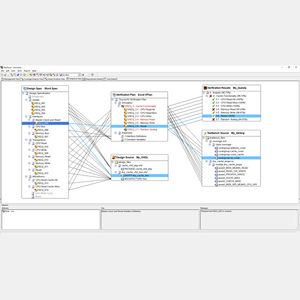
... Gerber AccuMark is a fully integrated suite of CAD software applications, from concept to completion. It enables fashion companies to develop collections with the perfect fit, at the right time. 2D Create, grade, ...
Gerber Technology, a Lectra company
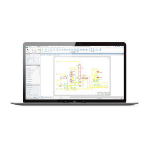
... What is OpenPlant PID? OpenPlant PID helps you produce intelligent piping and instrumentation diagrams faster and makes them widely accessible to all. Quickly accelerate your plant design process by: Using an intuitive user interface to reduce ...
Bentley Systems Europe B.V.
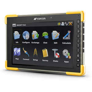
... Powerful layout, surveying, and construction workflows in the palm of your hand Easy to use and learn 3D layout Data handling Professional field-based, quality reporting Map-based workflows Hybrid GNSS and total stations control Harness the power ...

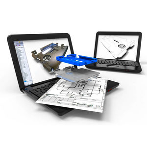
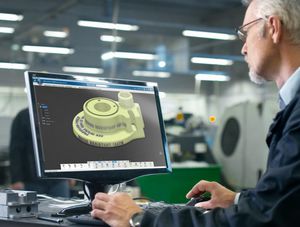
CAD (computer-aided design) software permits 2D and 3D product and process modeling, and precise visualization of a project idea or concept before its real-world production or construction. It also provides the opportunity to optimize technical parameters such as material strength, stress and heat dissipation characteristics.
ApplicationsThese programs are used in architecture, public works and infrastructure development, technical data management, industrial design and dynamic product simulation.
TechnologiesBasic CAD software offers independent 2D and 3D design capability, as well as design visualization including simplified views during development, object manipulation and representation of the finished product. The import and export of such models enable the integration of the objects into more complex designs. There are different programs available for mechanical engineering, architecture, electronics and other disciplines.
Basic versions can be augmented by complementary plug-ins for advanced analysis, simulation and other functions. Such modules are available from the original software manufacturer or from third-party suppliers.
Choice from among the many effective programs will depend on intended use, available functions and file types to ensure compatibility with client and supplier files.
- Permits digitization
- Simplifies improvements
- Increases storage capacity
- Facilitates file sharing
the best suppliers