
- Metrology - Laboratory
- Metrology and Test Equipment
- Metal pendulum impact tester
- ERICHSEN GmbH & Co. KG
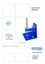
Metal pendulum impact tester Model 304 ISO-1

Add to favorites
Compare this product
Characteristics
- Applications
- for metals
Description
Description
Surface coatings are often exposed to impacts and impact stress in real-world practice. These can lead to deformation of the substrate and affect the adhesion and cohesion of the coating. Ball impact testers are used to test the resistance, deformability and ductility of coatings and substrates. They can also test the adhesion of coatings. The ball impact test provides a method to simulate this type of stress under standardized conditions by dropping a defined weight through a guide tube onto the specimen; the specimen-side end of the weight is designed as a ball head (for ASTM and ISO-1) or as a male tappet (for ISO-2) with a fixed diameter.
General Description
The Impact Tester, Model 304, consists of a sturdy base plate with an attached holding arm into which the slotted fall tube is clamped. In the ISO versions the clamp lever enables rapid setting for different specimen thicknesses and can be disengaged for free rotation. Below the falling tube and carried in the base plate is mounted the die in accordance with the relevant standard; the die is exchangeable and precisely fitted so that the centre lines of guide tube and die coincide. Located at the bottom end of the falling weight is the ball punch or male die tappet appropriate to the die being used. A lateral pin on the weight engages in the slot and is used to lift the weight manually to the desired height. On ISO versions the mass of the falling weight can be doubled by bolting on an additional weight (total up to 4 kg possible).
Procedure for the Impact Test
Specimens must be prepared as laid down in the relevant standards (surface treatment of base material, application and curing of coating, storage, coating thickness measurement, possible cross-cut test, etc.). Two fundamental choices must then be made:
Quantitative testing
A quantitative result is obtained by repeated impacts to establish the minimum energy causing damage. Drop distance (and thus impact energy) is varied until cracks and/or loss of adhesion appear. The energy value causing damage must be confirmed by repeated tests and additional panels; if results vary, calculate a mean value. Ensure tests are conducted at adequate distances from edges (at least 35 mm) and from previous tests on the specimen (minimum 70 mm centre to centre).
Evaluation and Interpretation
Deformed specimens are normally inspected visually for cracks and peeling, possibly with a magnifier. To reveal less obvious defects, ASTM D2794 suggests two more sensitive methods:
Energy units and conversion
Impact energy is expressed differently in standards. In ISO, DIN, NF and SNV the dropping height (mm) together with the weight is used for a relative scale. Other standards use absolute energy units: kg·m (ISO 6272, ASTM D2794) or inch·lbs (ASTM D2794). These units relate as follows: 0.1 kg·m = 8.8 inch·lbs. Due to differing ball and die dimensions, results from different ball impact methods cannot be converted precisely.
Standards
Accessories (selection shown on product page)
Technical characteristics / specifications
Surface coatings are often exposed to impacts and impact stress in real-world practice. These can lead to deformation of the substrate and affect the adhesion and cohesion of the coating. Ball impact testers are used to test the resistance, deformability and ductility of coatings and substrates. They can also test the adhesion of coatings. The ball impact test provides a method to simulate this type of stress under standardized conditions by dropping a defined weight through a guide tube onto the specimen; the specimen-side end of the weight is designed as a ball head (for ASTM and ISO-1) or as a male tappet (for ISO-2) with a fixed diameter.
General Description
The Impact Tester, Model 304, consists of a sturdy base plate with an attached holding arm into which the slotted fall tube is clamped. In the ISO versions the clamp lever enables rapid setting for different specimen thicknesses and can be disengaged for free rotation. Below the falling tube and carried in the base plate is mounted the die in accordance with the relevant standard; the die is exchangeable and precisely fitted so that the centre lines of guide tube and die coincide. Located at the bottom end of the falling weight is the ball punch or male die tappet appropriate to the die being used. A lateral pin on the weight engages in the slot and is used to lift the weight manually to the desired height. On ISO versions the mass of the falling weight can be doubled by bolting on an additional weight (total up to 4 kg possible).
Procedure for the Impact Test
Specimens must be prepared as laid down in the relevant standards (surface treatment of base material, application and curing of coating, storage, coating thickness measurement, possible cross-cut test, etc.). Two fundamental choices must then be made:
- The impact can be directed onto the coating side to produce a concave deformation (intrusion) or onto the reverse side to produce a convex deformation (extrusion); standards permit selection of either method or agreement between parties.
- For test energy, the first option is to set an agreed potential energy at the start of the fall. This provides a go/no-go or pass/fail result on the resistance of the coating to crack formation under rapid deformation and is qualitative, enabling rapid testing of batches.
Quantitative testing
A quantitative result is obtained by repeated impacts to establish the minimum energy causing damage. Drop distance (and thus impact energy) is varied until cracks and/or loss of adhesion appear. The energy value causing damage must be confirmed by repeated tests and additional panels; if results vary, calculate a mean value. Ensure tests are conducted at adequate distances from edges (at least 35 mm) and from previous tests on the specimen (minimum 70 mm centre to centre).
Evaluation and Interpretation
Deformed specimens are normally inspected visually for cracks and peeling, possibly with a magnifier. To reveal less obvious defects, ASTM D2794 suggests two more sensitive methods:
- Apply copper sulphate solution to the specimen to show the smallest coating faults in contrast; effective only if the substrate is steel and any anti-corrosion coating (e.g., phosphating) has been breached by the impact.
- For electrically insulating coatings on metallic substrates, examine the test area with a porosity test instrument; simple conductivity testers using a 9 VDC supply and a damp sponge probe are sufficient.
Energy units and conversion
Impact energy is expressed differently in standards. In ISO, DIN, NF and SNV the dropping height (mm) together with the weight is used for a relative scale. Other standards use absolute energy units: kg·m (ISO 6272, ASTM D2794) or inch·lbs (ASTM D2794). These units relate as follows: 0.1 kg·m = 8.8 inch·lbs. Due to differing ball and die dimensions, results from different ball impact methods cannot be converted precisely.
Standards
- ISO 6272-1
- ISO 6272-2
- ASTM D 2794
Accessories (selection shown on product page)
- ISO/IEC 17025 accredited calibration – Model 304 ISO (order option)
- ISO/IEC 17025 accredited calibration – Model 304 (additional weight) (order option)
- Retrofit kits (ISO-1 to ISO-2, ISO-1 to ASTM) (order options)
- Additional screw-on weights, hold/release device, safety fixing device and manufacturer test certificates (order options)
Technical characteristics / specifications
- Drive: Manual
- Die I.D.: 1.1" (27 mm)
- Ball Dia.: 0.79" (20 mm)
- Falling Weight: 1 + 1 kg (additional screw-on weight possible; total up to 4 kg with options)
- Scale / Division: 1000/5 mm
Catalogs

Exhibitions
Meet this supplier at the following exhibition(s):

Other ERICHSEN GmbH & Co. KG products
Impact Resistance


Related Searches
- ERICHSEN testing machine
- Measuring device
- ERICHSEN test chamber
- Test stand
- ERICHSEN temperature test chamber
- ERICHSEN material testing machine
- ERICHSEN automatic testing machine
- ERICHSEN hardness tester
- ERICHSEN climate chamber
- ERICHSEN quality control test chamber
- PC-controllable testing machine
- ERICHSEN portable tester
- ERICHSEN humidity test chamber
- ERICHSEN environmental test chamber
- Digital testing system
- Benchtop indentation hardness tester
- ERICHSEN industrial testing machine
- ERICHSEN vertical testing machine
- Automatic test stand
- Tensile test machine
*Prices are pre-tax. They exclude delivery charges and customs duties and do not include additional charges for installation or activation options. Prices are indicative only and may vary by country, with changes to the cost of raw materials and exchange rates.