

- Electricity - Electronics
- Electronic Component
- RF inductor
- Weilong Intelligent Technology (Dongguan) Co., Ltd.


- Company
- Products
- Catalogs
- News & Trends
- Exhibitions
Air core inductor WL1914RFairwire-wound

Add to favorites
Compare this product
Characteristics
- Technology
- air core, RF, air, wire-wound
- Electrical characteristics
- high-frequency, low-loss, RF
- Configuration
- through-hole type
- Applications
- for telecom applications, for electronics, EMI suppression, RFI suppression
- Other characteristics
- with round section wire, enameled round copper wire, round, encapsulated, copper, copper wire
Description
Product Overview
The WL1914 air core inductor coil is an electronic inductor formed by winding enameled copper wire into a coil without a magnetic core. Using air as the magnetic path eliminates core saturation and magnetic losses, making this component suited for high-frequency and RF applications. Available in multiple sizes, wire diameters and inductance values; OEM customization is supported.
Working Principle
An air core inductor operates by electromagnetic induction: current through the conductor generates a magnetic field around the coil. Variations in current produce changes in that field, creating inductive reactance that opposes rapid current changes. Inductance depends on number of turns, coil diameter, spacing and wire diameter.
Electrical Data (summary table)
Item — Description
Air core inductor coil — Enameled copper wire
Wire diameter — 0.20 mm (AWG options available)
Winding type — Single-layer round or sectional winding
Core material — Air (non-magnetic)
Footprint length — 15 mm
Encapsulation — Optional varnish, epoxy or coating
Mounting — Through-hole / custom options
Electrical Specifications (Typical)
Parameter — Description
Inductance range — 0.1 µH – 100 µH (customizable)
Inductance tolerance — ±2%, ±5%, ±10%
DC resistance (DCR) — Example: 14 Ω with 5.5 turns
Q factor — High, optimized for target frequency range
Self-resonant frequency — High, application dependent
Operating frequency — kHz to MHz range
Rated current — Defined per design
Insulation resistance — ≥100 MΩ
Features
Applications
Advantages & Limitations
Troubleshooting Notes
Common issues include unstable inductance from loose winding or incorrect spacing, overheating from excessive current or undersized wire, and EMI when placed too close to other components. Troubleshooting: inspect visually for damage, measure inductance and DCR, verify wire gauge and mounting/ventilation, and adjust winding spacing to reduce EMI.
Caractéristiques / Spécifications techniques
The WL1914 air core inductor coil is an electronic inductor formed by winding enameled copper wire into a coil without a magnetic core. Using air as the magnetic path eliminates core saturation and magnetic losses, making this component suited for high-frequency and RF applications. Available in multiple sizes, wire diameters and inductance values; OEM customization is supported.
Working Principle
An air core inductor operates by electromagnetic induction: current through the conductor generates a magnetic field around the coil. Variations in current produce changes in that field, creating inductive reactance that opposes rapid current changes. Inductance depends on number of turns, coil diameter, spacing and wire diameter.
Electrical Data (summary table)
Item — Description
Air core inductor coil — Enameled copper wire
Wire diameter — 0.20 mm (AWG options available)
Winding type — Single-layer round or sectional winding
Core material — Air (non-magnetic)
Footprint length — 15 mm
Encapsulation — Optional varnish, epoxy or coating
Mounting — Through-hole / custom options
Electrical Specifications (Typical)
Parameter — Description
Inductance range — 0.1 µH – 100 µH (customizable)
Inductance tolerance — ±2%, ±5%, ±10%
DC resistance (DCR) — Example: 14 Ω with 5.5 turns
Q factor — High, optimized for target frequency range
Self-resonant frequency — High, application dependent
Operating frequency — kHz to MHz range
Rated current — Defined per design
Insulation resistance — ≥100 MΩ
Features
- High-frequency performance suitable for RF circuits
- No magnetic core saturation or hysteresis
- Low core loss and distortion
- Stable inductance over operating range
- Compact and lightweight construction
- Fast electromagnetic response
- High Q factor for signal applications
- Adjustable size and inductance values
- Good thermal stability
Applications
- RF communications, transmitters and antennas
- Signal filters and oscillator circuits
- Audio systems (crossovers, high-end audio)
- Wireless charging and RF modules (including 5G components)
- Industrial electronics: sensing, control, filtering and power circuits
- Medical electronics requiring precise signal handling
- OEM components for compact and wearable devices
Advantages & Limitations
- Advantages: stable HF characteristics, no core losses or hysteresis, rapid response and easy customization
- Limitations: lower inductance per volume than iron-core inductors, may require more turns and exhibit higher copper losses at high currents; not optimal for low-frequency high-power use
Troubleshooting Notes
Common issues include unstable inductance from loose winding or incorrect spacing, overheating from excessive current or undersized wire, and EMI when placed too close to other components. Troubleshooting: inspect visually for damage, measure inductance and DCR, verify wire gauge and mounting/ventilation, and adjust winding spacing to reduce EMI.
Caractéristiques / Spécifications techniques
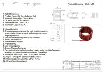
- Model: WL1914
- Core material: Air (non-magnetic)
- Conductor: Enameled copper wire
- Wire diameter: 0.20 mm (AWG options available)
- Winding type: Single-layer round or sectional winding
- Footprint length: 15 mm
- Encapsulation: Optional varnish, epoxy or coating
- Mounting: Through-hole or custom mounting options
- Inductance range: 0.1 µH – 100 µH (customizable)
- Inductance tolerance: ±2%, ±5%, ±10%
- DC resistance (example): 14 Ω with 5.5 turns
- Q factor: High (optimized per frequency)
- Operating frequency: kHz to MHz
- Rated current: Custom depending on design
- Insulation resistance: ≥100 MΩ
Catalogs
Other Weilong Intelligent Technology (Dongguan) Co., Ltd. products
Air Core Coil


Related Searches
- Transformer
- Dry transformer
- Encapsulated transformer
- Power transformer
- Isolation transformer
- Transformer for industrial applications
- Compact transformer
- Choke coil
- Electrical power supply transformer
- Transformer with copper windings
- Frequency inductor
- Wire-wound inductor
- Current inductor
- Electronic transformer
- Transformer for photovoltaic applications
- DC inductor
- Magnetic inductor
- Electronic inductor
- Power inductor
- Wire-wound choke
*Prices are pre-tax. They exclude delivery charges and customs duties and do not include additional charges for installation or activation options. Prices are indicative only and may vary by country, with changes to the cost of raw materials and exchange rates.
About DirectIndustry
DirectIndustry is a marketplace that offers B2B players a complete experience, from product sourcing to purchase. DirectIndustry is an entity of VirtualExpo Group.
Are you a buyer?
Are you a supplier?