
- Metrology - Laboratory
- Metrology and Test Equipment
- Voltage testing device
- Wuhan UHV Power Technology Co.,Ltd.
- Products
- Catalogs
- News & Trends
- Exhibitions
Secondary injection testing device UHV-802electricvoltagecurrent


Add to favorites
Compare this product
Characteristics
- Test type
- current, voltage, electric
- Operating mode
- computer-controlled, PC-controllable, computerized
- Test material
- relay, protection relay
- Technology
- secondary injection
- Configuration
- compact
- Other characteristics
- three-phase, stand-alone
Description
Product overview
Product Characteristics of Secondary Injection Relay Test Set
Product Parameters
Advantage of 3 Phase Relay Tester
Basic purpose of Relay Protection Tester
Routine maintenance of Relay Protection Tester
Applicable scenarios of relay protection tester
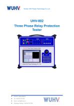
- The UHV-802 of Relay Protection Tester is a high-performance industrial control computer serves as the core controller, allowing direct operation of the Windows operating system. The tester is equipped with a 6.4-inch TFT true-color LCD display, a trackball, and an optimized keyboard on the front panel, enabling full operation without the need for an external mouse or keyboard.
- On the rear panel, the tester features a USB interface, a 10/100 Mbps Ethernet port, and a serial communication interface, facilitating convenient data access, communication, and software upgrades.
- The entire testing process and results are clearly displayed on the LCD screen. The system provides a full English operational interface that is user-friendly and intuitive. Operation is carried out using the built-in trackball and keyboard, making it simple, convenient, and easy to learn—requiring only basic computer knowledge from the operator.
- For users who prefer external peripherals, the front panel also includes keyboard and mouse interfaces. By connecting an external mouse and keyboard, the tester can be operated just like a standard desktop computer.
Product Characteristics of Secondary Injection Relay Test Set
- Flexible Voltage and Current Output: Features standard 4-phase voltage and 3-phase current output, enabling a variety of combined outputs for different types of protection tests. Each phase voltage can output up to 120V, and the three-phase current combined output can reach 120A. The fourth-phase voltage Ux is a multifunctional channel, configurable as 3U0, a synchronization voltage, or any specified voltage value as needed.
- Easy Operation: The device panel is equipped with a trackball mouse, an optimized keyboard, and a large-screen TFT LCD display. It comes with a built-in full English Windows platform operating software, allowing immediate use upon startup with simple operation.
- Dual Operation Modes: In addition to standalone operation, the device can be connected to an external laptop or desktop computer. Both operating modes offer fully consistent functionality, providing true dual-mode versatility.
- High-Fidelity Linear Power Amplifier: The output consistently utilizes high-fidelity, high-reliability modular linear power amplifiers rather than switching power amplifiers, delivering excellent performance. This design eliminates high- and medium-frequency interference to the test site and ensures smooth waveforms across the entire current range, from large to small values.
- High-Performance Host Platform: The output section is controlled by a DSP, offering fast operation, strong real-time digital signal processing capability, wide transmission bandwidth, and high-resolution D/A conversion. This results in high output waveform precision, low distortion, and excellent linearity. The device incorporates advanced technologies, precision components, and high-quality materials, with a professional structural design that ensures compact size, light weight, full functionality, and easy portability. Ready for immediate use, it is highly convenient for on-site testing.
- Powerful Software Capabilities: The software supports a wide range of large-scale, highly automated calibration tasks. It enables easy testing and scanning of various protection settings, fault playback, real-time test data storage, vector diagram display, online report printing, and more.
- Independent Dedicated DC Power Output: The device includes a dedicated adjustable DC power output, providing both 110V and 220V outputs as standard.
- Comprehensive Interfaces: The device panel features a built-in keyboard and mouse for standalone operation, while external keyboard and mouse can also be connected via dedicated interfaces. It is also equipped with two USB ports and RS232 ports for communication with computers and other external devices.
- Comprehensive Self-Protection Features: The device incorporates a well-designed heat dissipation structure, reliable and comprehensive hardware protection measures, and power soft-start functionality. Software-based fault self-diagnosis and output lock features further enhance operational safety.
- Lightweight, Highly Integrated Design: Utilizing a large number of advanced technologies and a meticulously designed ultra-light, compact structure, the device achieves an exceptionally small size and light weight, making it highly portable and easy to handle.
Product Parameters
- AC current output
- Phase current output (effective value): 0~40A
- Output Precision: 0.2 degree
- 3 phase parallel current output (effective value): 0~120A
- A Long-time Phase current: 450VA
- Maximum output power of 3 parallel current: 900VA
- Maximum Permitted work time of 3 parallel current: 10s
- Frequency range ( fundamental): 0~1000Hz
- Harmonic time: 0~20
- DC current output
- Output current: 0±10A / phase, 0±30A / 3 parallel
- Output Precision: 0.5 degree
- Maximum output load voltage: 20V
- AC voltage output
- Phase voltage output (effective value): 0~120V
- Output Precision: 0.2 degree
- Line voltage output (effective value): 0~240V
- Phase voltage / Line phase output power: 80VA / 100VA
- Frequency range (fundamental): 0~1000Hz
- Harmonic time: 0~20
- DC voltage output
- Phase voltage output range: 0±160V
- Output Precision: 0.5 degree
- Line voltage output range: 0±320V
- Phase voltage / Line phase output power: 70VA / 140VA
Advantage of 3 Phase Relay Tester
- High precision testing
- Comprehensive functionality
- Efficient automatic testing
- Convenient Operation
- compact and lightweight
- Easy to maintain
- High reliability and stability
Basic purpose of Relay Protection Tester
- The microcomputer relay protection tester is mainly used for the calibration, testing, and debugging of relay protection equipment. In the power system, relay protection devices play an important role in fault detection and removal, and their effectiveness directly affects the safety and stability of the power system. Through a microcomputer relay protection tester, engineers can simulate various power system faults such as short circuits, overloads, and disconnections to verify whether the relay protection equipment can correctly identify and take corresponding protection measures. The Relay Protection Tester simulates the changes in current and voltage under different fault conditions to detect the accuracy of the relay's action, ensuring that it can timely and effectively cut off the faulty part during actual operation and avoid larger scale power system accidents.
Routine maintenance of Relay Protection Tester
- Appearance inspection: Regularly inspect the appearance of the relay protection tester to confirm that there are no issues such as damage, deformation, scratches, etc., and that all components are tightly connected without any looseness.
- Cleaning: Regularly clean the surface of the relay protection tester and keep it clean and dry. Use a soft cloth to wipe the surface of the instrument, avoiding the use of irritating or overly rough fabrics.
- Interface protection: For connecting terminals, they should be regularly checked for looseness, oxidation, or damage. If any problems are found, the terminals should be replaced in a timely manner to ensure stable and reliable interface connections.
- Battery level: Regularly check the battery level of the relay protection tester to ensure sufficient battery capacity. If the battery level is found to be too low, it should be charged promptly and good usage habits should be maintained.
Applicable scenarios of relay protection tester
- Power engineering company: undertakes preventive testing and handover testing of substations.
- Large industrial and mining enterprises (such as steel, petrochemical, data centers): daily operation and maintenance of their own substations.
- Motor manufacturing factory and cabinet factory: factory testing and calibration of relay protection devices.
- University Electrical Laboratory: Teaching Demonstration and Research Experiment.
VIDEO
Catalogs
Other Wuhan UHV Power Technology Co.,Ltd. products
Relay Protection Tester


Related Searches
- Measuring device
- Test stand
- Portable testing system
- Digital testing system
- Automatic test stand
- Automatic testing system
- Industrial testing system
- Automatic test equipment
- Portable measuring device
- Voltage testing system
- Industrial gauge
- Benchtop testing system
- Manual test kit
- Test set
- Industrial test equipment
- Portable test kit
- Industrial test rig
- Insulation testing system
- Cabling tester
- Tester with LCD screen
*Prices are pre-tax. They exclude delivery charges and customs duties and do not include additional charges for installation or activation options. Prices are indicative only and may vary by country, with changes to the cost of raw materials and exchange rates.