
- Electricity - Electronics
- Switch and Relay
- Electromechanical relay module
- Romutec Steuer- u. Regelsysteme GmbH
Switching relay module FE02DCACelectromechanical

Add to favorites
Compare this product
Characteristics
- Type
- switching, DC, AC, electromechanical
- Other characteristics
- with LED indicator
- Load current
Max.: 5 A
Min.: 0 A
- Load voltage
Max.: 24 V
Min.: 8 V
Description
Product information
Functional unit FE02 provides a manual control level with an emergency function for a single-stage drive. The module includes a slide switch with positions Auto‑0‑1; in delivery state the Auto position is potential‑free and routed to the terminal. Manual feedback routing can be changed internally via jumper J1. A potential‑free changeover relay per control unit permits direct switching of power contactors. The relay in Auto is controlled by a DDC/PLC output. An LED indicates relay status; LED colour (red or green) is selectable via jumper J2 and can trigger a collective message on an FE04 via jumper J3. Relay control voltage in delivery state: 8–24 V AC/DC. Control with GND (AC‑COM) can be enabled via jumper J4. Jumpers are located inside the module and are accessible after carefully opening the enclosure with a flat‑head screwdriver.
Function / Features
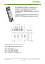
Terminal designations and electrical data
Terminals are numbered according to the module position within the enclosure (e.g. 3.6 = slot 3, terminal 6). In the following list X denotes the module position.
Mechanical data
External dimensions (W × H × D): 17.5 × 90 × 58 mm.
Additional notes
Observe relay contact load limits when switching power contactors. Jumpers are located inside the module and require careful opening of the enclosure to change. LED colour selection and collective message triggering are available via dedicated jumpers.
Technical specifications
Functional unit FE02 provides a manual control level with an emergency function for a single-stage drive. The module includes a slide switch with positions Auto‑0‑1; in delivery state the Auto position is potential‑free and routed to the terminal. Manual feedback routing can be changed internally via jumper J1. A potential‑free changeover relay per control unit permits direct switching of power contactors. The relay in Auto is controlled by a DDC/PLC output. An LED indicates relay status; LED colour (red or green) is selectable via jumper J2 and can trigger a collective message on an FE04 via jumper J3. Relay control voltage in delivery state: 8–24 V AC/DC. Control with GND (AC‑COM) can be enabled via jumper J4. Jumpers are located inside the module and are accessible after carefully opening the enclosure with a flat‑head screwdriver.
Function / Features
- Manual control level with emergency function for single‑stage drive
- Slide switch positions: Auto - 0 - 1
- Auto position potential‑free and routed to terminal in delivery state
- Internal jumper J1: change switch feedback routing for manual position
- Potential‑free changeover relay per control unit for direct switching of power contactors (observe contact load)
- Relay controlled by DDC/PLC output in Auto position
- LED indicator for relay status; colour selectable via jumper J2 (red or green)
- LED can trigger collective message on FE04 via jumper J3
- Relay control voltage (delivery state): 8 V to 24 V AC/DC
- Selectable control with GND (AC‑COM) via jumper J4
- Jumpers accessible inside module (changeable after careful opening of enclosure)
Terminal designations and electrical data
Terminals are numbered according to the module position within the enclosure (e.g. 3.6 = slot 3, terminal 6). In the following list X denotes the module position.
- Terminal X.1: Supply voltage GND
- Terminal X.2: Supply voltage 24 V AC or DC
- Terminal X.3, X.4: Switch feedback in Auto or Manual position, potential‑free, max. 28 V AC/DC, max. 5 A, 100 VA
- Terminal X.5: Relay NC contact
- Terminal X.6: Relay control input, 8 V to 24 V AC or DC. Control with GND (AC‑COM) selectable via J4.
- Terminal X.7: Relay NO contact
- Terminal X.8: Relay COM (root), max. 250 V AC, max. 5 A, 1250 VA
Mechanical data
External dimensions (W × H × D): 17.5 × 90 × 58 mm.
Additional notes
Observe relay contact load limits when switching power contactors. Jumpers are located inside the module and require careful opening of the enclosure to change. LED colour selection and collective message triggering are available via dedicated jumpers.
Technical specifications
- Model designation: FE02
- Function: Single‑stage drive manual control level with emergency function
- Switch positions: Auto - 0 - 1
- Relay: potential‑free changeover contact per control unit
- Control voltage (delivery state): 8 V to 24 V AC/DC
- Switch feedback contacts (X.3, X.4): potential‑free, max. 28 V AC/DC, max. 5 A, 100 VA
- Relay COM (X.8): max. 250 V AC, max. 5 A, 1250 VA
- Selectable control mode: GND (AC‑COM) via jumper J4
- LED status indicator with selectable colour via J2; collective message via J3
- Jumpers: J1 (feedback manual), J2 (LED colour), J3 (collective message), J4 (GND control)
- External dimensions: 17.5 × 90 × 58 mm (W × H × D)
- Weight: 0.061 kg
Catalogs
E10_FE
5 Pages
Other Romutec Steuer- u. Regelsysteme GmbH products
Local Priority Operating Level DIN Rail


*Prices are pre-tax. They exclude delivery charges and customs duties and do not include additional charges for installation or activation options. Prices are indicative only and may vary by country, with changes to the cost of raw materials and exchange rates.