

- Robotics - Automation - Industrial IT
- Automation
- RFID antenna
- Weilong Intelligent Technology (Dongguan) Co., Ltd.


- Company
- Products
- Catalogs
- News & Trends
- Exhibitions
RF antenna WL1225RFIDAMrod

Add to favorites
Compare this product
Characteristics
- Network
- RF, RFID, AM
- Type
- rod
- Other characteristics
- passive, compact, portable, high-performance
- Applications
- for vehicles, measurement, for IoT applications
- Frequency
Max.: 1,000 kHz
Min.: 1 kHz
Description
Overview
A compact ferrite coil antenna engineered for reliable reception in low- and medium-frequency applications. Built with a high-permeability ferrite rod and precision enameled copper winding to concentrate magnetic flux and improve sensitivity. Configurable for OEM and industrial use by selecting frequency range, inductance, core dimensions, number of turns and mounting method.
How it works
The antenna converts changing RF magnetic fields into voltage by electromagnetic induction: the ferrite rod concentrates flux and the copper winding produces an electrical signal. Compared with air-core coils of similar size, the ferrite core provides higher effective permeability, enabling reception of weaker signals. The coil and external tuning components form a resonant circuit to optimize selectivity and reduce interference.
Main features
Applications
Advantages
Disadvantages / Limitations
Troubleshooting & Common Issues
Product Datasheet (key entries)
Item - Description
Ferrite Coil Inductor - Enameled copper wire
Wire Diameter - 0.2 mm (other AWG options available)
Winding Type - Single-layer round or sectional winding
Core Material - Ferrite rod
Footprint length - 25 mm
Encapsulation - Optional varnish, epoxy or coating
Mounting - Through-foot / custom
Electrical Specifications (Typical)
Parameter - Description
Inductance Range - 0.1 µH – 100 µH (customizable)
Inductance Tolerance - ±2%, ±5%, ±10%
DCR - Custom (design dependent)
Q Factor - High, optimized for frequency range
Self-Resonant Frequency - Application dependent
Operating Frequency - kHz to MHz range
Rated Current - Specified per design
Insulation Resistance - ≥100 MΩ
FAQs (selected)
Technical specifications
A compact ferrite coil antenna engineered for reliable reception in low- and medium-frequency applications. Built with a high-permeability ferrite rod and precision enameled copper winding to concentrate magnetic flux and improve sensitivity. Configurable for OEM and industrial use by selecting frequency range, inductance, core dimensions, number of turns and mounting method.
How it works
The antenna converts changing RF magnetic fields into voltage by electromagnetic induction: the ferrite rod concentrates flux and the copper winding produces an electrical signal. Compared with air-core coils of similar size, the ferrite core provides higher effective permeability, enabling reception of weaker signals. The coil and external tuning components form a resonant circuit to optimize selectivity and reduce interference.
Main features
- High magnetic sensitivity from ferrite core
- Compact footprint (25 mm example) for embedded and portable devices
- Low power loss and high Q factor when optimized for the target band
- Customizable winding, inductance, wire gauge and core dimensions
- Optional encapsulation (varnish, epoxy, coating) for environmental protection
- Mounting options: through-foot or custom fixtures
Applications
- AM radio receivers and portable radios
- RFID readers, access control and identification systems
- IoT devices, smart meters and wireless sensors
- Automotive electronics (keyless entry, TPMS, navigation)
- Industrial automation: wireless sensors and machine monitoring
- Consumer electronics requiring LF/MF reception
Advantages
- High magnetic-field reception in a small package
- Good frequency selectivity and stable electrical behavior
- Low sensitivity to radiated electric fields when integrated correctly
- Parameters can be tailored to OEM specifications
- Long operational life with proper handling
Disadvantages / Limitations
- Narrower intrinsic bandwidth than some broadband antennas; requires correct tuning
- Performance affected by nearby metal and placement
- Ferrite material is brittle and can fracture under mechanical shock
- Requires quality ferrite material and careful tuning for optimal results
Troubleshooting & Common Issues
- Poor reception: verify orientation, winding continuity and core integrity
- Frequency mismatch: check inductance, number of turns and tuning capacitors
- High noise: evaluate placement, shielding and local interference sources
- Reduced sensitivity: inspect winding quality and ferrite grade
- Mechanical damage: avoid impacts during assembly and transport
Product Datasheet (key entries)
Item - Description
Ferrite Coil Inductor - Enameled copper wire
Wire Diameter - 0.2 mm (other AWG options available)
Winding Type - Single-layer round or sectional winding
Core Material - Ferrite rod
Footprint length - 25 mm
Encapsulation - Optional varnish, epoxy or coating
Mounting - Through-foot / custom
Electrical Specifications (Typical)
Parameter - Description
Inductance Range - 0.1 µH – 100 µH (customizable)
Inductance Tolerance - ±2%, ±5%, ±10%
DCR - Custom (design dependent)
Q Factor - High, optimized for frequency range
Self-Resonant Frequency - Application dependent
Operating Frequency - kHz to MHz range
Rated Current - Specified per design
Insulation Resistance - ≥100 MΩ
FAQs (selected)
- What is the coil antenna used for? — Reception of LF and MF magnetic signals: AM radio, RFID, wireless sensors, smart meters and automotive systems.
- Why use ferrite? — Ferrite increases magnetic permeability to concentrate flux and enhance sensitivity compared with air-core coils.
- How to choose the right coil? — Define operating frequency, required inductance/Q, core size, wire gauge, mounting and environmental constraints.
- Can it be customized? — Yes: rod length/diameter, ferrite grade, winding construction, inductance and mounting options can be tailored for OEM needs.
Technical specifications
- Model: WL1225 (custom winding)
- Core type: Ferrite rod
- Footprint length: 25 mm
- Wire: Enameled copper wire (example 0.2 mm; other sizes available)
- Winding: Single-layer round or sectional; customizable turns
- Inductance range: 0.1 µH – 100 µH (customizable)
- Inductance tolerance: ±2%, ±5%, ±10%
- Operating frequency: kHz to MHz (design dependent)
- Q factor: High, optimized for chosen frequency
- DCR: As specified per design
- Rated current: As specified per design
- Insulation resistance: ≥100 MΩ
- Encapsulation: Optional varnish, epoxy or coating
- Mounting: Through-foot or custom mounting available
Catalogs
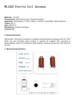
WL1225 Ferrite Coil Antenna
3 Pages
Other Weilong Intelligent Technology (Dongguan) Co., Ltd. products
Ferrite Coil


*Prices are pre-tax. They exclude delivery charges and customs duties and do not include additional charges for installation or activation options. Prices are indicative only and may vary by country, with changes to the cost of raw materials and exchange rates.
About DirectIndustry
DirectIndustry is a marketplace that offers B2B players a complete experience, from product sourcing to purchase. DirectIndustry is an entity of VirtualExpo Group.
Are you a buyer?
Are you a supplier?