

- Electricity - Electronics
- Electronic Component
- Ferrite inductor
- Weilong Intelligent Technology (Dongguan) Co., Ltd.


- Company
- Products
- Catalogs
- News & Trends
- Exhibitions
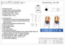
Ferrite inductor WL0710magneticwire-woundferrite core

Add to favorites
Compare this product
Characteristics
- Technology
- ferrite, magnetic, wire-wound, ferrite core
- Electrical characteristics
- inductive, high-frequency, EMI
- Configuration
- through-hole type, printed circuit
- Applications
- for switching power supplies, for DC/DC converters, EMI suppression, for telecom applications, for automotive applications
- Other characteristics
- copper wire, enameled round copper wire, encapsulated, epoxy resin
Description
Product Overview
Ferrite coil inductor WL0710 is a passive magnetic component consisting of enameled copper wire wound on a ferrite core. It stores energy in a magnetic field and controls current and noise in electronic circuits. Ferrite cores provide high magnetic permeability and low core loss at high frequencies, making these inductors suitable for power electronics, EMI filtering and signal conditioning in industrial applications.
How Ferrite Coil Inductor Works
The inductor converts electrical energy to magnetic energy by current flowing through the copper winding. The ferrite core concentrates magnetic flux and increases inductance. Changes in current induce a counter-voltage (Lenz’s law), opposing rapid current variations. Ferrite materials reduce eddy-current losses at higher frequencies, improving filtering and noise suppression.
Main Features
Product Datasheet (Key Items)
Item: Ferrite coil inductor WL0710
Description: Enameled copper wire winding on ferrite core
Wire diameter: 0.8 mm (AWG options available)
Winding type: Single-layer round or sectional
Core material: Ferrite magnetic rod
Footprint length: 8 mm
Encapsulation: Optional varnish, epoxy or coating
Mounting: Through-foot / custom options
Electrical Specifications (Typical)
Inductance range: 0.1 µH – 100 µH (customizable)
Inductance tolerance: ±2%, ±5%, ±10%
DC resistance (DCR): design-dependent
Q factor: Optimized per frequency range
Self-resonant frequency: Application-dependent (typically high)
Operating frequency: kHz to MHz range
Rated current: Specified per design to avoid saturation
Insulation resistance: ≥100 MΩ
Industrial Applications
Suitable for switching power supplies (SMPS), DC–DC converters, EMI/RFI filters, telecommunications, automotive electronics (ECUs, infotainment, EV systems), industrial drives and control systems, renewable energy inverters and consumer electronics where compact noise suppression is required.
Advantages & Disadvantages
Troubleshooting
Check for core saturation when DC or peak currents exceed design limits (inductance drop, heating). Verify PCB placement, grounding and shielding for EMI issues. Measure inductance and DCR with an LCR meter to detect manufacturing variance or damage. Inspect core for cracks; replace if damaged. Use thermal inspection to locate hotspots and confirm thermal design.
Selection Guidance & Design Tips
Define target inductance and required current rating early. Select ferrite grade appropriate to the operating frequency to minimize core loss. Provide adequate margin for DC bias to prevent saturation. Optimize winding and minimize DCR to reduce I²R losses. Consider shielded versions in noisy layouts and ensure proper PCB land pattern for thermal and mechanical stability. Prototype and validate under real operating conditions.
Inductance Calculation Methods
Basic A_L method:
L = A_L × N² (L in nH, A_L in nH/N², N = number of turns). Example: A_L = 250 nH/N² and N = 10 → L = 250 × 100 = 25000 nH = 25 µH.
Magnetic-circuit (reluctance) method:
L = N² / ℛ_total where ℛ_total = ℛ_core + ℛ_gap and ℛ = l / (μ0 × μr × A). Introducing an air gap increases reluctance, reduces inductance and helps prevent core saturation under DC bias. Account for frequency dependence of μr, DC bias effects and fringing fields.
Notes
Inductance and losses depend on operating frequency, DC bias and temperature; select materials and geometry according to application requirements and validate experimentally.
Technical Specifications
Ferrite coil inductor WL0710 is a passive magnetic component consisting of enameled copper wire wound on a ferrite core. It stores energy in a magnetic field and controls current and noise in electronic circuits. Ferrite cores provide high magnetic permeability and low core loss at high frequencies, making these inductors suitable for power electronics, EMI filtering and signal conditioning in industrial applications.
How Ferrite Coil Inductor Works
The inductor converts electrical energy to magnetic energy by current flowing through the copper winding. The ferrite core concentrates magnetic flux and increases inductance. Changes in current induce a counter-voltage (Lenz’s law), opposing rapid current variations. Ferrite materials reduce eddy-current losses at higher frequencies, improving filtering and noise suppression.
Main Features
- High magnetic permeability and low core loss at kHz–MHz frequencies
- Compact, lightweight bobbin suitable for space-constrained PCBs
- Effective EMI suppression for power and signal lines
- Available in multiple geometries and customizable dimensions
- Optional encapsulation (varnish, epoxy) and mounting styles
Product Datasheet (Key Items)
Item: Ferrite coil inductor WL0710
Description: Enameled copper wire winding on ferrite core
Wire diameter: 0.8 mm (AWG options available)
Winding type: Single-layer round or sectional
Core material: Ferrite magnetic rod
Footprint length: 8 mm
Encapsulation: Optional varnish, epoxy or coating
Mounting: Through-foot / custom options
Electrical Specifications (Typical)
Inductance range: 0.1 µH – 100 µH (customizable)
Inductance tolerance: ±2%, ±5%, ±10%
DC resistance (DCR): design-dependent
Q factor: Optimized per frequency range
Self-resonant frequency: Application-dependent (typically high)
Operating frequency: kHz to MHz range
Rated current: Specified per design to avoid saturation
Insulation resistance: ≥100 MΩ
Industrial Applications
Suitable for switching power supplies (SMPS), DC–DC converters, EMI/RFI filters, telecommunications, automotive electronics (ECUs, infotainment, EV systems), industrial drives and control systems, renewable energy inverters and consumer electronics where compact noise suppression is required.
Advantages & Disadvantages
- Advantages: Good high-frequency performance, reduced core losses, compact form factor, effective EMI suppression, customizable construction.
- Disadvantages: Possible core saturation under high DC bias (reducing inductance), material-dependent losses at extreme frequencies, mechanical fragility in harsh vibration environments, potential non-linear behavior compared to air-core options.
Troubleshooting
Check for core saturation when DC or peak currents exceed design limits (inductance drop, heating). Verify PCB placement, grounding and shielding for EMI issues. Measure inductance and DCR with an LCR meter to detect manufacturing variance or damage. Inspect core for cracks; replace if damaged. Use thermal inspection to locate hotspots and confirm thermal design.
Selection Guidance & Design Tips
Define target inductance and required current rating early. Select ferrite grade appropriate to the operating frequency to minimize core loss. Provide adequate margin for DC bias to prevent saturation. Optimize winding and minimize DCR to reduce I²R losses. Consider shielded versions in noisy layouts and ensure proper PCB land pattern for thermal and mechanical stability. Prototype and validate under real operating conditions.
Inductance Calculation Methods
Basic A_L method:
L = A_L × N² (L in nH, A_L in nH/N², N = number of turns). Example: A_L = 250 nH/N² and N = 10 → L = 250 × 100 = 25000 nH = 25 µH.
Magnetic-circuit (reluctance) method:
L = N² / ℛ_total where ℛ_total = ℛ_core + ℛ_gap and ℛ = l / (μ0 × μr × A). Introducing an air gap increases reluctance, reduces inductance and helps prevent core saturation under DC bias. Account for frequency dependence of μr, DC bias effects and fringing fields.
Notes
Inductance and losses depend on operating frequency, DC bias and temperature; select materials and geometry according to application requirements and validate experimentally.
Technical Specifications
- Model: WL0710
- Core material: Ferrite (magnetic rod)
- Winding: Enameled copper wire, single-layer round or sectional
- Wire diameter: 0.8 mm (AWG options available)
- Footprint length: 8 mm
- Encapsulation options: Varnish, epoxy or coating
- Mounting: Through-foot or custom
- Inductance range: 0.1 µH – 100 µH (customizable)
- Tolerance: ±2%, ±5%, ±10%
- Operating frequency: kHz to MHz
- Rated current: Custom per design
- Insulation resistance: ≥100 MΩ
- Q factor: High (optimized for frequency range)
Catalogs
Other Weilong Intelligent Technology (Dongguan) Co., Ltd. products
Ferrite Coil


Related Searches
- Transformer
- Dry transformer
- Encapsulated transformer
- Power transformer
- Isolation transformer
- Transformer for industrial applications
- Compact transformer
- Choke coil
- Electrical power supply transformer
- Transformer with copper windings
- Frequency inductor
- Wire-wound inductor
- Current inductor
- Electronic transformer
- Transformer for photovoltaic applications
- DC inductor
- Magnetic inductor
- Electronic inductor
- Power inductor
- Wire-wound choke
*Prices are pre-tax. They exclude delivery charges and customs duties and do not include additional charges for installation or activation options. Prices are indicative only and may vary by country, with changes to the cost of raw materials and exchange rates.
About DirectIndustry
DirectIndustry is a marketplace that offers B2B players a complete experience, from product sourcing to purchase. DirectIndustry is an entity of VirtualExpo Group.
Are you a buyer?
Are you a supplier?