
{{product.productLabel}} {{product.model}}
{{#if product.featureValues}}{{product.productPrice.formattedPrice}} {{#if product.productPrice.priceType === "PRICE_RANGE" }} - {{product.productPrice.formattedPriceMax}} {{/if}}
{{#each product.specData:i}}
{{name}}: {{value}}
{{#i!=(product.specData.length-1)}}
{{/end}}
{{/each}}
{{{product.idpText}}}

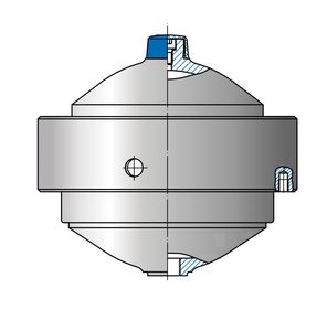
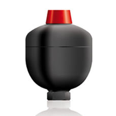
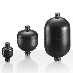
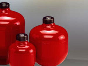
... The This series is a good alternative to a diaphragm accumulator as it is can provide enhanced nitrogen gas retention and has a compact and lightweight design. Although these accumulators are offered in standard ...
... Overview
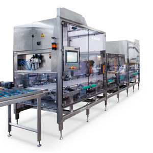
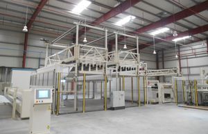
The Franz Haas HEIP inline wafer block buffer absorbs jams caused by short production interruptions and temporarily stores wafer blocks for later reintroduction without upstream production loss.
Key benefits
- Saving
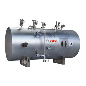
... Bosch Steam accumulator module SAM - For covering short-term peak loads - Compensates for brief power peaks - Reduces water entrainment and counteracts its negative effects - Reduces switching frequency of steam generator - Reduces ...

... recommendations for hydraulic accumulators. You can download the accumulator sizing software from the Product Support tab. Key Markets: • Industrial • Mobile • Renewable Energy • Power Generation • Oil & Gas • ...
Parker Electromechanical and Drives Division Europ

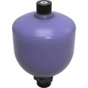
... Diaphragm accumulator size 0.7 liters, 210 bar for mobile and industrial applications Diaphragm accumulator, according to PED 2014/68/EU article 4(3): CE certificate not required. For pressure shock and vibration absorption, ...
Bosch Rexroth - Industrial Hydraulics
... The integral diaphragm accumulators are well-developed. They vary in permissible operation pressure, nominal volume, diaphragm materials (gas pre-load) and fluid connection. The series offers a lot of advantages: accumulator ...
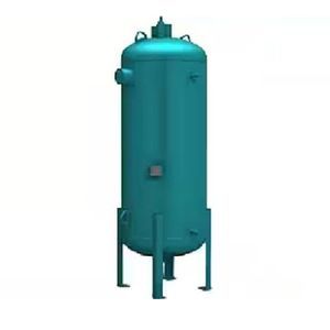
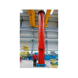
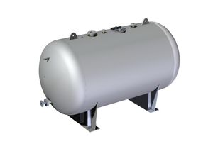
... paint system with a high-gloss finish. Vertical Accumulators Elevate your industrial refrigeration with the protection of a vertical accumulator. Engineered for clean and safe operation, our accumulators ...
... In accumulators liquids are stored under pressure. By discharging energy can thus be taken from the accumulator. Accumulators can be used e.g. as an emergency function, for damping of vibrations and ...

... The steam accumulator ATTSU AV series can be adapted to different volumes according to installation. The steam accumulator ATTSU AV series is equipped by complete valve set, instrumentation, water visual levels, electrodes, ...
... In HIDRACAR bladder type accumulators, the separator element is a rubber bladder; normally nitrile rubber, but it can be made in other materials. The body is made in carbon steel. Our bladder type accumulators sealing ...
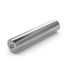
... HIDRACAR piston type accumulators are the strongest and most reliable oleo-pneumatic accumulators in the market. They are made in carbon steel and the separator element is a piston made in aluminium. Made in a range ...

... expansion, in machine tools, etc… Oleo-pneumatic accumulators are used in hydraulic applications in all types of sectors: Agricultural, chemical, transport, energy, etc… Oleo-pneumatic accumulators are normally ...
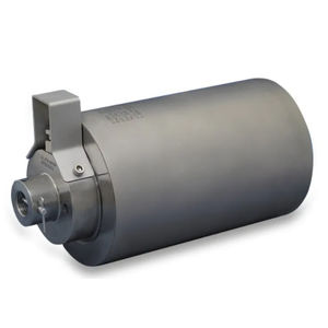
... The Cross GO Series piston type hydro-pneumatic accumulators are energy storage devices which are used to provide auxiliary and emergency power and to absorb or suppress hydraulic system shock pressures. These nitrogen gas-charged units ...

... pressures up to 330 bar), these hydropneumatic accumulators represent a particularly attractive solution for mobile applications. Available for useful volumes from 0.7 to 4 Litres, the ACS(L) accumulators series are available ...
HYDRO LEDUC
... Douce-Hydro also specializes in the design and manufacture of piston accumulators, offering the following technological advantages: high compression ratio, reliability, long term storage capabilities, customs capacity and volume up to ...

... Execution 480 Bar / 690 Bar - Execution with nitrogen/poppet valve in inox - Execution for additional nitrogen bottle - Accumulators technically and dimensionally interchangeable with other brands of same type ...
Fox S.r.l.
... ACCUMULATOR Published in Non-woven All our accumulators are equipped with motorised carriages for light-weight fabrics (50gr/m2) Electronic web tension system enables us to store all settings in recipes. When loading ...
... Operating pressure: WA 0.05>3.8 max 50/330 bar WA 0.05>3.8 (Fig. II) max 50/330 bar WA 0.75>3.8 (Fig. III) max 50/330 bar WA 0.05>3.8 (Fig. IV) max 50/330 bar Gas filling (nitrogen only): max. 90% of min. operating pressure ...
SAIP S.R.L.
... , diaphragm is fitted into the accumulator shell. An inert gas - nitrogen - is filled into the diaphragm through a pressure valve to a pressure P . The diaphragm expands,0 filling the entire volume V of the accumulator ...
EPE Process Filters & Accumulators Pvt. Ltd.
Byworth Boilers has manufactured the Steam Tank applicable when the user is running a little short on steam. These devices serve as a buffer for steam storage, even in outing the load on the boiler, in processes where the steam demand shows characteristic ...
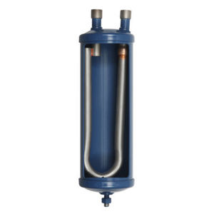
... suction line accumulators LCY and LCYE are particularly recommended for installations that are: ➜ exposed to sudden thermal load variations, ➜ whose piping lengths are important, ➜ operating with cycle inversions. The LCYE suction accumulators ...
CARLY
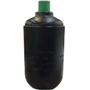
... Maximum working pressure (PS): 300 bar Test pressure (PT): PS x 1.43 bar Maximum préchargé admissible: 210 bar Body: made in painted carbon Steel Standard nitrogen valve : W UNF Constructive methodology: two différent parts united whit a spécial ...
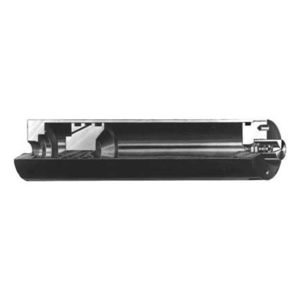
... A hydro-pneumatic accumulator is a device used specifically for storage of liquid under pressure. Since liquids, for all practical purposes, are incompressible, this is achieved by using the compressibility of gases. A flexible rubber ...
OMT Group
... Bubble accumulators, diaphragm accumulators, piston accumulators. We support you in dimensioning as well as in selecting the right type. We also offer a pressure accumulator service incl. ...
... The NuQuip® A-Series Accumulator is a piston-style accumulator available in three sizes with two maximum working pressure choices. Accumulators are used for dampening pulsation in pressure systems, or ...

... Suction Line Accumulator is to prevent a sudden surge of liquid refrigerant or oil form returning down the suction line and into a compressor. The suction line accumulator is a temporary reservoir for liquid refrigerant ...
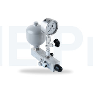
... Features The DHE consists of an accumulator, a pressure gauge with a shut-off valve and a check valve. The DHE can also be retrofitted to a SPA (Conversion kit no.: DHE140/R001-00). Advantages Suitable for retrofitting to a SPA system ...
the best suppliers