
- Electricity - Electronics
- Electronic Component
- Ferrite inductor
- Weilong Intelligent Technology (Dongguan) Co., Ltd.
- Company
- Products
- Catalogs
- News & Trends
- Exhibitions
Ferrite inductor WL0243wire-woundlow-frequencycircular


Add to favorites
Compare this product
Characteristics
- Technology
- wire-wound, ferrite
- Electrical characteristics
- low-frequency
- Configuration
- square, circular
- Applications
- wireless power charging
- Other characteristics
- copper, enameled round copper wire
- Primary current
Max.: 3 A
Min.: 1 A
Description
Product overview
Wireless charging coil WL0243 is a flat spiral receiving/transmitting coil for inductive power transfer. It is wound with enameled copper wire and can include ferrite sheet shielding to reduce EMI and concentrate magnetic flux. The design targets compact electronic devices and industrial modules where space, thermal behaviour and repeatable electrical characteristics are critical.
Features
Electrical specifications
Mechanical specifications
Available models (mechanical dimensions)
Applications
Suitable for inductive charging in smartphones, tablets, wearables, wireless earbuds, in-vehicle phone chargers, smart home devices, certain medical devices requiring dustproof/waterproof integration and industrial equipment where wireless power simplifies connections and reduces mechanical wear.
Benefits and Drawbacks
How to choose
Technical specifications
Wireless charging coil WL0243 is a flat spiral receiving/transmitting coil for inductive power transfer. It is wound with enameled copper wire and can include ferrite sheet shielding to reduce EMI and concentrate magnetic flux. The design targets compact electronic devices and industrial modules where space, thermal behaviour and repeatable electrical characteristics are critical.
Features
- Precisely wound enameled copper wire for consistent magnetic performance
- Stable inductance with quality factor Q ≥ 30
- Low DC resistance (DCR) to reduce conduction losses
- Ferrite sheet shielding option to lower EMI and improve coupling
- Flat spiral geometry for low profile integration
- Customizable outer/inner diameter, wire gauge and nominal inductance
- Terminal options: solder pad or lead wire; mounting by adhesive fixing
Electrical specifications
- Inductance (L): 300–500 µH
- Inductance tolerance: ±5%
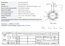
- Test frequency: 125 kHz (additional 0.25 kHz noted in datasheet context)
- DC Resistance (DCR): 80–250 mΩ
- Rated current (Irms): 1–3 A
- Operating frequency: 85–205 kHz
- Quality factor (Q): ≥ 30
- Insulation resistance: ≥ 100 MΩ
Mechanical specifications
- Coil shape: round or square
- Wire type: enameled copper wire
- Shielding: ferrite sheet (optional)
- Insulation: PET or PI film
- Terminal type: solder pad or lead wire
- Mounting: adhesive fixing
Available models (mechanical dimensions)
- WL 35 — Outer diameter 35 mm / Inner diameter 15 mm / Thickness 2.0 mm
- WL 43 — Outer diameter 43 mm / Inner diameter 20 mm / Thickness 2.0 mm
- WL 50 — Outer diameter 50 mm / Inner diameter 25 mm / Thickness 3.0 mm
Applications
Suitable for inductive charging in smartphones, tablets, wearables, wireless earbuds, in-vehicle phone chargers, smart home devices, certain medical devices requiring dustproof/waterproof integration and industrial equipment where wireless power simplifies connections and reduces mechanical wear.
Benefits and Drawbacks
- Benefits: eliminates mechanical connectors, enables sealed/dustproof designs, consistent electrical parameters, flexible form-factor and customisation.
- Drawbacks: lower end-to-end efficiency vs wired charging, potential heat if misaligned, limited transfer distance requiring close coil alignment, added control circuitry complexity.
How to choose
- Match coil inductance and tolerance to the wireless charging controller and target operating frequency.
- Design for the intended operating frequency (typical Qi-range ≈ 85–205 kHz).
- Balance wire diameter to manage DCR and thermal rise while meeting size constraints.
- Choose appropriate ferrite shielding thickness to minimise EMI and optimise coupling.
- Select outer/inner diameters and thickness based on device space and power requirements.
Technical specifications
- Inductance range: 300–500 µH
- Inductance tolerance: ±5%
- Test frequency: 125 kHz (with 0.25 kHz noted)
- DCR: 80–250 mΩ
- Rated current: 1–3 A
- Operating frequency: 85–205 kHz
- Q factor: ≥ 30
- Insulation resistance: ≥ 100 MΩ
- Shapes: round or square, flat spiral
- Wire: enameled copper
- Shielding: ferrite sheet
- Insulation materials: PET / PI film
- Terminals: solder pad or lead wire
- Mounting: adhesive fixing
- Model dimensions: WL 35 (Ø outer 35 mm / inner 15 mm / thickness 2.0 mm), WL 43 (Ø outer 43 mm / inner 20 mm / thickness 2.0 mm), WL 50 (Ø outer 50 mm / inner 25 mm / thickness 3.0 mm)
VIDEO
Catalogs
Other Weilong Intelligent Technology (Dongguan) Co., Ltd. products
Ferrite Coil Inductor Antenna


Related Searches
- Frequency inductor
- Wire-wound inductor
- Magnetic inductor
- Electronic inductor
- Magnetic Helmholtz coil
- Copper Helmholtz coil
- Ferrite inductor
- Industrial inductor
- SMT inductor
- Switching power supply inductor
- Current coil
- Small inductor
- Custom-made inductor
- Copper inductor
- HF inductor
- AC Helmholtz coil
- Coil for telecom applications
- Solenoid valve coil
- EMI suppression inductor
- Voltage coil
*Prices are pre-tax. They exclude delivery charges and customs duties and do not include additional charges for installation or activation options. Prices are indicative only and may vary by country, with changes to the cost of raw materials and exchange rates.