

- Electricity - Electronics
- Electronic Component
- Air core coil
- Weilong Intelligent Technology (Dongguan) Co., Ltd.


- Company
- Products
- Catalogs
- News & Trends
- Exhibitions
Air core coil WL3049high-frequencyRFlow-loss

Add to favorites
Compare this product
Characteristics
- Technology
- air core
- Electrical characteristics
- inductive, high-frequency, RF, low-loss
- Configuration
- low-profile, through-hole type
- Applications
- industrial, for automotive applications, for electronics, for inverters, energy storage, for switching power supplies, for solar inverters, for DC/DC converters
- Other characteristics
- copper, copper wire, rectangular copper wire
Description
Overview
A flat copper coil is an electrical component made by winding flat (rectangular or ribbon-like) copper conductors into coil forms, spiral patterns, or multiple layers. Flat copper coils offer larger surface area and lower resistance compared to conventional round-wire coils, improving efficiency, heat dissipation, and current capacity. They can be manufactured in customized sizes, shapes and inductance values and finished with varnish, epoxy or other protective coatings.
Key uses and applications
Product Datasheet
Compact Flat Copper Coil | Description: Enameled copper ribbon
Wire Diameter | 0.20 (AWG options available)
Winding Type | Single-layer round or sectional winding
Core Material | Air (non-magnetic)
Footprint length | 15 mm
Encapsulation | Optional varnish, epoxy, or coating
Mounting | Through-hole / Custom
Electrical Specifications (Typical)
Inductance Range | 0.1 µH – 100 µH (customizable)
Inductance Tolerance | ±2%, ±5%, ±10%
DC Resistance (DCR) | Example: 14 Ω with 5.5 turns
Q Factor | High, optimized for frequency range
Self-Resonant Frequency | High, application-dependent
Operating Frequency | kHz to MHz range
Rated Current | Custom per design
Insulation Resistance | ≥100 MΩ
How it works
The flat copper coil operates on electromagnetic induction: current through the coil generates a magnetic field that stores and transfers energy and can induce currents in adjacent conductors. The flat conductor geometry increases surface area and reduces AC resistance (skin and proximity effects), making these coils suitable for high-frequency and high-current applications.
Characteristics of flat copper coils
Advantages
Limitations / Disadvantages
Troubleshooting
Selection and design guidance
Technical characteristics / specifications
A flat copper coil is an electrical component made by winding flat (rectangular or ribbon-like) copper conductors into coil forms, spiral patterns, or multiple layers. Flat copper coils offer larger surface area and lower resistance compared to conventional round-wire coils, improving efficiency, heat dissipation, and current capacity. They can be manufactured in customized sizes, shapes and inductance values and finished with varnish, epoxy or other protective coatings.
Key uses and applications
- Wireless charging systems (smartphones, wearables, EV wireless charging)
- Power electronics: DC-DC converters, inverters, switching power supplies
- RF systems and high-frequency transformers
- Automotive electronics: on-board chargers, battery management systems, EV power electronics
- Medical electronics: imaging systems, monitoring and precision devices
- Industrial automation: sensors, control equipment, robotics, IoT/Industry 4.0 devices
- Renewable energy: solar inverters, energy storage converters
Product Datasheet
Compact Flat Copper Coil | Description: Enameled copper ribbon
Wire Diameter | 0.20 (AWG options available)
Winding Type | Single-layer round or sectional winding
Core Material | Air (non-magnetic)
Footprint length | 15 mm
Encapsulation | Optional varnish, epoxy, or coating
Mounting | Through-hole / Custom
Electrical Specifications (Typical)
Inductance Range | 0.1 µH – 100 µH (customizable)
Inductance Tolerance | ±2%, ±5%, ±10%
DC Resistance (DCR) | Example: 14 Ω with 5.5 turns
Q Factor | High, optimized for frequency range
Self-Resonant Frequency | High, application-dependent
Operating Frequency | kHz to MHz range
Rated Current | Custom per design
Insulation Resistance | ≥100 MΩ
How it works
The flat copper coil operates on electromagnetic induction: current through the coil generates a magnetic field that stores and transfers energy and can induce currents in adjacent conductors. The flat conductor geometry increases surface area and reduces AC resistance (skin and proximity effects), making these coils suitable for high-frequency and high-current applications.
Characteristics of flat copper coils
- Lower DC resistance due to larger cross-sectional copper area
- Improved heat dissipation because of increased surface area
- Compact, low-profile designs enabling space-efficient integration
- High power density and mechanical stability
- Customizable sizes, shapes, and inductance values
Advantages
- Increased electrical efficiency (lower DCR)
- Improved thermal performance and lower operating temperature
- Better performance at high frequencies (reduced skin and proximity losses)
- Higher current carrying capacity and higher power density
- Supports automated precision manufacturing for consistency
Limitations / Disadvantages
- Manufacturing is more complex and typically costlier versus round-wire coils
- Flat conductors are less flexible, complicating some winding geometries
- Requires specialized winding/forming equipment and careful design to avoid parasitic effects
- Incorrect design or insulation application can cause uneven fields or reliability issues
Troubleshooting
- Minimal inductance: check for physical damage, incorrect design, or EMI sources
- Overheating: verify operating current, cooling and mounting, and thermal design
- Lower efficiency: inspect connections, oxidation, and high-frequency losses
- Open circuit: measure resistance to detect broken conductors or solder joint failures
- Short circuit: check insulation between windings and replace or rewind if internal shorts occur
- EMC issues: install shielding or increase separation from interfering components
Selection and design guidance
- Define electrical requirements first: inductance, resistance, max current, voltage, and operating frequency
- Assess thermal performance and thermal management needs for continuous operation
- Check available installation space and mounting options (through-hole vs custom)
- Consider environmental conditions (temperature, humidity, vibration) and required protective coatings
- Request manufacturer quality data and customization options when specific inductance/size/current ratings are required
- Balance cost versus performance; custom designs may increase lead time and unit cost
Technical characteristics / specifications
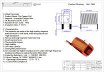
- Model: WL3049
- Conductor: enameled copper flat/ribbon
- Wire diameter: 0.20 mm (AWG options available)
- Winding: single-layer round or sectional winding
- Core material: air (non-magnetic)
- Footprint length: 15 mm
- Encapsulation: varnish / epoxy / coating (optional)
- Mounting: through-hole or custom
- Inductance range: 0.1 µH – 100 µH (customizable)
- Inductance tolerance: ±2%, ±5%, ±10%
- DCR example: 14 Ω (with 5.5 turns)
- Operating frequency: kHz to MHz
- Insulation resistance: ≥100 MΩ
- Rated current: defined per custom design
Catalogs
Other Weilong Intelligent Technology (Dongguan) Co., Ltd. products
Ferrite Coil Inductor Antenna


Related Searches
- Frequency inductor
- Wire-wound inductor
- Magnetic inductor
- Electronic inductor
- Magnetic Helmholtz coil
- Copper Helmholtz coil
- Ferrite inductor
- Industrial inductor
- SMT inductor
- Switching power supply inductor
- Current coil
- Small inductor
- Custom-made inductor
- Copper inductor
- HF inductor
- AC Helmholtz coil
- Coil for telecom applications
- Solenoid valve coil
- EMI suppression inductor
- Voltage coil
*Prices are pre-tax. They exclude delivery charges and customs duties and do not include additional charges for installation or activation options. Prices are indicative only and may vary by country, with changes to the cost of raw materials and exchange rates.