

- Electricity - Electronics
- Electronic Component
- Ferrite inductor
- Weilong Intelligent Technology (Dongguan) Co., Ltd.


- Company
- Products
- Catalogs
- News & Trends
- Exhibitions
Ferrite inductor WL0710ferrite coremagneticwire-wound

Add to favorites
Compare this product
Characteristics
- Technology
- wire-wound, magnetic, ferrite, ferrite core
- Electrical characteristics
- high-frequency, EMI, RF
- Configuration
- through-hole type
- Applications
- for electronics, industrial, for switching power supplies, EMI suppression, for automotive applications, for telecom applications, for inverters
- Other characteristics
- copper, enameled round copper wire, encapsulated, with round section wire, epoxy resin
Description
Overview
Ferrite coil inductor is a passive component formed by an enameled copper winding around a ferrite magnetic core. It stores energy in a magnetic field and regulates current in electronic circuits. Ferrite materials provide high permeability and low core loss at high frequencies, improving inductor performance in power and signal applications.
Product Overview
These inductors are designed for energy storage, filtering and EMI suppression. Construction combines a ferrite magnetic rod core with single-layer or sectional copper winding. Available in multiple geometries and customizable windings, the WL0710 series suits compact PCB designs and switching circuits where stable inductance and low electrical noise are required.
How It Works
When current flows through the copper winding, electrical energy is converted to magnetic energy in the ferrite core. The core’s high relative permeability increases inductance; variations in current induce a counter-voltage (Lenz’s law) that opposes sudden current changes. Ferrite composition reduces eddy current losses at high frequencies, making these inductors effective for smoothing and noise suppression.
Main Features
Applications
Advantages and Disadvantages
Troubleshooting
Technical datasheet (summary)
Item: Ferrite Coil Inductor
Wire: Enameled copper wire
Wire Diameter: 0.8 mm (AWG options available)
Winding Type: Single-layer round or sectional winding
Core Material: Ferrite magnetic rod
Footprint length: 8 mm
Encapsulation: Optional varnish, epoxy or coating
Mounting: Through-foot or custom mounting
Electrical Specifications (Typical)
Inductance Range: 0.1 µH – 100 µH (customizable)
Inductance Tolerance: ±2%, ±5%, ±10%
DC Resistance (DCR): Custom per design
Q Factor: High, optimized for intended frequency range
Self-Resonant Frequency: High, application-dependent
Operating Frequency: kHz to MHz range
Rated Current: Defined per design (consider DC bias and saturation)
Insulation Resistance: ≥100 MΩ
HOW TO SELECT A FERRITE COIL INDUCTOR (key points)
Calculation & Design Tips (summary)
Use the inductance factor A_L for initial sizing: L = A_L × N² (L in nH, N = turns). For improved accuracy apply magnetic-circuit reluctance models: ℛ = l / (μ0 × μr × A) and L = N² / ℛ_total, including air-gap reluctance. Account for DC bias, frequency dependence of permeability and fringing effects when designing for high DC currents or wide frequency ranges.
Caractéristiques / Spécifications techniques
Ferrite coil inductor is a passive component formed by an enameled copper winding around a ferrite magnetic core. It stores energy in a magnetic field and regulates current in electronic circuits. Ferrite materials provide high permeability and low core loss at high frequencies, improving inductor performance in power and signal applications.
Product Overview
These inductors are designed for energy storage, filtering and EMI suppression. Construction combines a ferrite magnetic rod core with single-layer or sectional copper winding. Available in multiple geometries and customizable windings, the WL0710 series suits compact PCB designs and switching circuits where stable inductance and low electrical noise are required.
How It Works
When current flows through the copper winding, electrical energy is converted to magnetic energy in the ferrite core. The core’s high relative permeability increases inductance; variations in current induce a counter-voltage (Lenz’s law) that opposes sudden current changes. Ferrite composition reduces eddy current losses at high frequencies, making these inductors effective for smoothing and noise suppression.
Main Features
- High magnetic permeability and low core losses at kHz–MHz frequencies
- Compact, lightweight construction suitable for space-constrained PCBs
- Effective EMI suppression for noisy environments
- High achievable inductance values with ferrite core
- Options for varnish, epoxy or other encapsulation and various mounting types
Applications
- Switching power supplies (SMPS) and voltage regulation systems
- Telecommunications equipment for filtering and EMI control
- Automotive electronics (ECUs, infotainment, EV control units)
- Industrial automation: motor drives, PLCs and control circuits
- Renewable energy inverters (solar, wind)
- Consumer electronics requiring compact noise control (smartphones, laptops, LED drivers)
Advantages and Disadvantages
- Advantages: good high-frequency performance, reduced core losses, compact size, strong EMI suppression
- Disadvantages: potential saturation under high DC bias (reducing inductance), material-dependent losses at extreme frequencies, possible mechanical fragility in harsh environments, some non-linear behavior under heavy bias
Troubleshooting
- Check for core saturation if inductance drops or the part overheats under high current
- Verify PCB placement and grounding to optimize EMI performance
- Measure inductance and DCR with LCR meter to confirm specifications
- Inspect core for cracks or mechanical damage and replace if necessary
- Use thermal imaging to detect hotspots and validate thermal behaviour
Technical datasheet (summary)
Item: Ferrite Coil Inductor
Wire: Enameled copper wire
Wire Diameter: 0.8 mm (AWG options available)
Winding Type: Single-layer round or sectional winding
Core Material: Ferrite magnetic rod
Footprint length: 8 mm
Encapsulation: Optional varnish, epoxy or coating
Mounting: Through-foot or custom mounting
Electrical Specifications (Typical)
Inductance Range: 0.1 µH – 100 µH (customizable)
Inductance Tolerance: ±2%, ±5%, ±10%
DC Resistance (DCR): Custom per design
Q Factor: High, optimized for intended frequency range
Self-Resonant Frequency: High, application-dependent
Operating Frequency: kHz to MHz range
Rated Current: Defined per design (consider DC bias and saturation)
Insulation Resistance: ≥100 MΩ
HOW TO SELECT A FERRITE COIL INDUCTOR (key points)
- Define required inductance and operating frequency range
- Consider maximum current and DC bias to avoid core saturation
- Choose ferrite material grade suited to the frequency to minimize core losses
- Verify temperature stability for automotive and industrial requirements
- Evaluate size and packaging for compact device constraints
- Ensure low DCR to reduce I²R losses and heating
- Consider shielding in EMI-sensitive applications
- Prototype and test under real operating conditions
Calculation & Design Tips (summary)
Use the inductance factor A_L for initial sizing: L = A_L × N² (L in nH, N = turns). For improved accuracy apply magnetic-circuit reluctance models: ℛ = l / (μ0 × μr × A) and L = N² / ℛ_total, including air-gap reluctance. Account for DC bias, frequency dependence of permeability and fringing effects when designing for high DC currents or wide frequency ranges.
Caractéristiques / Spécifications techniques
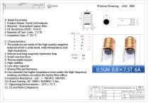
- Model: WL0710
- Core material: Ferrite (magnetic rod)
- Winding: Enameled copper wire, single-layer round or sectional
- Typical wire diameter: 0.8 mm (AWG options available)
- Footprint length: 8 mm
- Encapsulation: Optional varnish, epoxy or coating
- Mounting: Through-foot or custom
- Inductance range: 0.1 µH – 100 µH (customizable)
- Tolerance options: ±2%, ±5%, ±10%
- DC resistance (DCR): Custom per design
- Q factor: High, optimized for intended frequency
- Operating frequency: kHz to MHz range
- Self-resonant frequency: High (application dependent)
- Rated current: Custom per design (consider DC bias and saturation)
- Insulation resistance: ≥100 MΩ
Catalogs
Other Weilong Intelligent Technology (Dongguan) Co., Ltd. products
Ferrite Coil Inductor Antenna


Related Searches
- Frequency inductor
- Wire-wound inductor
- Magnetic inductor
- Electronic inductor
- Magnetic Helmholtz coil
- Copper Helmholtz coil
- Ferrite inductor
- Industrial inductor
- SMT inductor
- Switching power supply inductor
- Current coil
- Small inductor
- Custom-made inductor
- Copper inductor
- HF inductor
- AC Helmholtz coil
- Coil for telecom applications
- Solenoid valve coil
- EMI suppression inductor
- Voltage coil
*Prices are pre-tax. They exclude delivery charges and customs duties and do not include additional charges for installation or activation options. Prices are indicative only and may vary by country, with changes to the cost of raw materials and exchange rates.