



- Company
- Products
- Catalogs
- News & Trends
- Exhibitions
Variable shunt reactor ICR-Himmersedoil-immersed

Add to favorites
Compare this product
Characteristics
- Type
- variable
- Construction
- immersed, oil-immersed
- Voltage
Max.: 35 kV
Min.: 10 kV
Description
• IEC 60076-6, IEEE Std. C57.21, NEMA
• ISO 9001, KEMA, CESI, CE, TUV, UL, ASTA
• Seismic design, ETGI-1.020, IEEE Std 693, NCh2369
• Structural design, ASTM A325, ANSI/AISC 360, AWS D1.1
• High altitude correction per IEC 60076 & IEEE C57, ~ 5000m
• Reactive power compensation (power factor correction) in networks with harmonics
• Reduction of inrush currents that flow from step to step of the capacitor banks when switched
• Decrease the level of harmonic distortion as the circuit is also having a certain tuning frequency
• Avoiding the risk of resonance as the LC circuit has a resonance frequency below the first existing harmonic
• Iron core reactor portfolio: HV harmonic filter reactors, HV detuned filter reactors, HV tuned filter reactors
Iron Core Reactor
An Iron Core Reactor is an electrical reactor (inductor) that uses a magnetic iron or steel core to increase inductance and magnetic flux concentration. It is designed to provide controlled inductive impedance for reactive power compensation, current limiting, harmonic filtering, and voltage regulation in power systems.
Unlike an Air Core Reactor, the iron core provides a low-reluctance magnetic path, allowing a smaller physical size for the same inductance value.
1. Working Principle
When alternating current flows through the reactor winding:
·The coil produces a magnetic field.
·The iron core concentrates and strengthens the magnetic flux.
·The stored magnetic energy creates inductive reactance that limits current or absorbs reactive power.
2. Main Construction
Magnetic Core
·Laminated silicon steel core
·Reduces eddy current losses
·Designed to avoid excessive saturation
Windings
·Copper or aluminum conductors
·Insulated layer winding or disc winding
·Designed for thermal and mechanical strength
Insulation System
·Dry-type insulation or oil insulation
·Depending on voltage and application
Cooling System
·Natural air cooling (AN)
·Forced air cooling (AF)
·Oil cooling (ONAN/ONAF) for large units
3. Types of Iron Core Reactors
A.) Iron Core Shunt Reactor
Purpose:
·Absorbs excess reactive power from transmission lines
·Controls overvoltage caused by cable capacitance
Applications:
·Extra-high voltage transmission systems
·Underground cable networks
Typical ratings:
·35 kV to 765 kV
·Several MVAR capacity
B.) Iron Core Current Limiting Reactor
Purpose:
·Increases system impedance
·Limits short-circuit current
Applications:
·Generator output circuits
·Bus-tie connections
·Industrial power networks
Benefits:
·Protects circuit breakers and transformers
·Reduces fault energy
C.) Iron Core Filter Reactor
Purpose:
·Reduces harmonic currents
·Smooths converter output
Applications:
·HVDC systems
·Rectifier stations
·Industrial converters
D.) Iron Core Smoothing Reactor
Used in DC systems to:
·Reduce current ripple
·Improve DC current stability
Applications:
·HVDC transmission
·Battery energy storage systems
4. Advantages
·High inductance density: Smaller size compared with air core
·Compact design: Requires less installation space
·Strong magnetic coupling: Efficient energy storage
·Suitable for low-frequency systems: Effective at 50/60 Hz
·High reactive power capability: Suitable for large compensation systems
5. Typical Specifications
·Voltage class: 6 kV – 765 kV
·Frequency: 50/60 Hz
·Capacity: kVAR to hundreds of MVAR
·Core material: Silicon steel
·Cooling: Air or oil cooling
·Installation: Indoor/outdoor
·Insulation: Dry-type or oil immersed
6. Applications
·Transmission line voltage control
·Reactive power compensation
·Capacitor bank protection
·Harmonic filtering
·HVDC converter stations
·Industrial power systems
·Renewable energy plants
·Arc furnace installations
Iron Core Reactor summary:
An Iron Core Reactor is a high-inductance reactor using a laminated magnetic core to achieve compact and powerful reactive control. It is commonly used in high-voltage transmission systems, shunt compensation, and large-scale power quality applications where high inductance and high reactive power capability are required.
• ISO 9001, KEMA, CESI, CE, TUV, UL, ASTA
• Seismic design, ETGI-1.020, IEEE Std 693, NCh2369
• Structural design, ASTM A325, ANSI/AISC 360, AWS D1.1
• High altitude correction per IEC 60076 & IEEE C57, ~ 5000m
• Reactive power compensation (power factor correction) in networks with harmonics
• Reduction of inrush currents that flow from step to step of the capacitor banks when switched
• Decrease the level of harmonic distortion as the circuit is also having a certain tuning frequency
• Avoiding the risk of resonance as the LC circuit has a resonance frequency below the first existing harmonic
• Iron core reactor portfolio: HV harmonic filter reactors, HV detuned filter reactors, HV tuned filter reactors
Iron Core Reactor
An Iron Core Reactor is an electrical reactor (inductor) that uses a magnetic iron or steel core to increase inductance and magnetic flux concentration. It is designed to provide controlled inductive impedance for reactive power compensation, current limiting, harmonic filtering, and voltage regulation in power systems.
Unlike an Air Core Reactor, the iron core provides a low-reluctance magnetic path, allowing a smaller physical size for the same inductance value.
1. Working Principle
When alternating current flows through the reactor winding:
·The coil produces a magnetic field.
·The iron core concentrates and strengthens the magnetic flux.
·The stored magnetic energy creates inductive reactance that limits current or absorbs reactive power.
2. Main Construction
Magnetic Core
·Laminated silicon steel core
·Reduces eddy current losses
·Designed to avoid excessive saturation
Windings
·Copper or aluminum conductors
·Insulated layer winding or disc winding
·Designed for thermal and mechanical strength
Insulation System
·Dry-type insulation or oil insulation
·Depending on voltage and application
Cooling System
·Natural air cooling (AN)
·Forced air cooling (AF)
·Oil cooling (ONAN/ONAF) for large units
3. Types of Iron Core Reactors
A.) Iron Core Shunt Reactor
Purpose:
·Absorbs excess reactive power from transmission lines
·Controls overvoltage caused by cable capacitance
Applications:
·Extra-high voltage transmission systems
·Underground cable networks
Typical ratings:
·35 kV to 765 kV
·Several MVAR capacity
B.) Iron Core Current Limiting Reactor
Purpose:
·Increases system impedance
·Limits short-circuit current
Applications:
·Generator output circuits
·Bus-tie connections
·Industrial power networks
Benefits:
·Protects circuit breakers and transformers
·Reduces fault energy
C.) Iron Core Filter Reactor
Purpose:
·Reduces harmonic currents
·Smooths converter output
Applications:
·HVDC systems
·Rectifier stations
·Industrial converters
D.) Iron Core Smoothing Reactor
Used in DC systems to:
·Reduce current ripple
·Improve DC current stability
Applications:
·HVDC transmission
·Battery energy storage systems
4. Advantages
·High inductance density: Smaller size compared with air core
·Compact design: Requires less installation space
·Strong magnetic coupling: Efficient energy storage
·Suitable for low-frequency systems: Effective at 50/60 Hz
·High reactive power capability: Suitable for large compensation systems
5. Typical Specifications
·Voltage class: 6 kV – 765 kV
·Frequency: 50/60 Hz
·Capacity: kVAR to hundreds of MVAR
·Core material: Silicon steel
·Cooling: Air or oil cooling
·Installation: Indoor/outdoor
·Insulation: Dry-type or oil immersed
6. Applications
·Transmission line voltage control
·Reactive power compensation
·Capacitor bank protection
·Harmonic filtering
·HVDC converter stations
·Industrial power systems
·Renewable energy plants
·Arc furnace installations
Iron Core Reactor summary:
An Iron Core Reactor is a high-inductance reactor using a laminated magnetic core to achieve compact and powerful reactive control. It is commonly used in high-voltage transmission systems, shunt compensation, and large-scale power quality applications where high inductance and high reactive power capability are required.
Catalogs
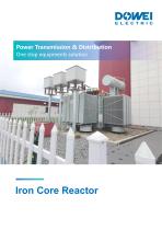
Other Dowei Electric products
Reactor & Line Trap


Related Searches
- Transformer
- Dry transformer
- Capacitor
- Circuit breaker
- IEC transformer
- Current transformer
- Generator
- Encapsulated transformer
- Power transformer
- Single-phase transformer
- Industrial transformer
- Three-phase transformer
- Floor-standing transformer
- Instrument transformer
- Protection transformer
- Cast resin transformer
- Switchgear
- Transformer for industrial applications
- Indoor service transformer
- Current circuit breaker
*Prices are pre-tax. They exclude delivery charges and customs duties and do not include additional charges for installation or activation options. Prices are indicative only and may vary by country, with changes to the cost of raw materials and exchange rates.
About DirectIndustry
DirectIndustry is a marketplace that offers B2B players a complete experience, from product sourcing to purchase. DirectIndustry is an entity of VirtualExpo Group.
Are you a buyer?
Are you a supplier?