
{{product.productLabel}} {{product.model}}
{{#if product.featureValues}}{{product.productPrice.formattedPrice}} {{#if product.productPrice.priceType === "PRICE_RANGE" }} - {{product.productPrice.formattedPriceMax}} {{/if}}
{{#each product.specData:i}}
{{name}}: {{value}}
{{#i!=(product.specData.length-1)}}
{{/end}}
{{/each}}
{{{product.idpText}}}
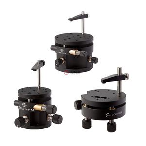
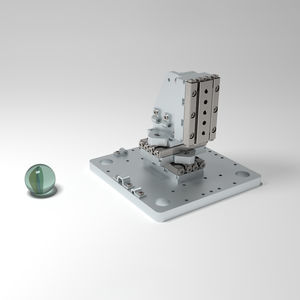
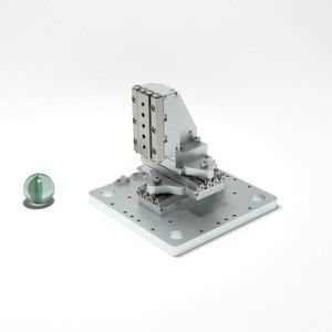
... The Tip Tilt and Rotation Stages provide ±4˚ or ±5˚ uncoupled tilt adjustment in pitch and roll. The resolution of single-axis is 2 arcmin or 10 arcmin. These adjustments allow optical components and fixtures to be aligned with a plane ...
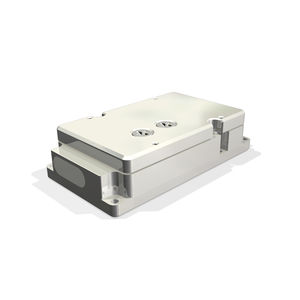
Stroke : 5, 25, 15 mm
Speed: 1.5, 1 mm/s
Repeatability: 0.25, 2 µm
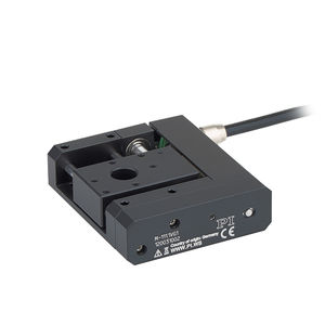
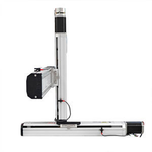
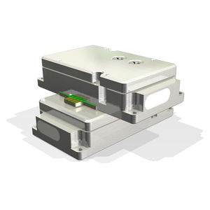
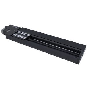
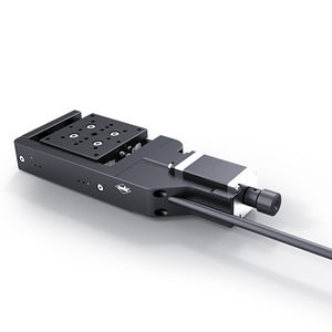
... Closed-loop DC motors Noncontact reference and limit switches XY setups can be mounted directly Compact linear stage, versatile in use Linear stage with compact size due to folded drive with belt drive. Clear ...
Physik Instrumente
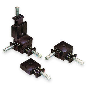
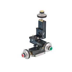
... used with an XYZ stage, it provides six degrees of freedom for total positioning capability. Model 39 provides two axes of angular adjustments, allowing a mounted component to be oriented parallel to ...

Stroke : 50 mm - 1,500 mm
Speed: 500 mm/s
Repeatability: 0.02 mm
... Ball Screw Module, Belt Driven Linear Guide, Positioning Stage, Motion Controller for Cartesian Robot. CE, FCC, RoHS, ISO9001 Certification. Wide Variety of Ready-to-Ship Products Quantity Discounts Starting ...
FUYU Technology
Stroke : 50 mm - 1,000 mm
Speed: 0 m/s - 0.26 m/s
Repeatability: 0.02 mm - 0.2 mm
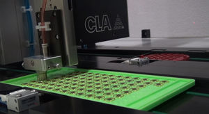
... Product overview
Motorized multi-axis
XYZ
positioning stage FSK40IS-DL, designed for precise point-to-point handling,
positioning, inspection and dispensing tasks. Effective travel: X 200 mm, ...
FUYU Technology
Stroke : 50 mm - 1,250 mm
Speed: 0 m/s - 0.4 m/s
Load: 50,000 g - 80,000 g
... Overview
The FTH14
XYZ-T T-type 3-axis motion platform by Fuyu Technology Co., Ltd. is a motorized ball-screw linear actuator
stage engineered for precise
positioning in inspection and imaging ...
FUYU Technology
Stroke : 0 mm - 200 mm
Load: 1, 2, 5 kg
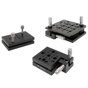
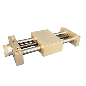
... Economical manual positioning table drived by leadscrew. Actuated by grip knob. Guided by 2 rods on bronze bearings. Options : Positioning indicator Position clamping Base plate (with or without ...

Stroke : 0 mm - 300 mm
Load: 3, 7, 12, 20 kg
... Manual lifting table Driving by leadscrew Guided by 2 rods Options : Handwheel or grip knob Positioning indicator Position clamping Assembly in XY or XYZ table Interest of lifting table These tables can be ...

Stroke : 0 mm - 300 mm
Speed: 0.02 m/s - 0.25 m/s
Load: 3, 6, 12, 23 kg
... Assembly of tables in XZ, YZ or XYZ systems For a crossed table XZ, the tables are mounted on one another directly by the body with the option 308922* (smooth holes are made in the body of a table). For YZ or XYZ ...
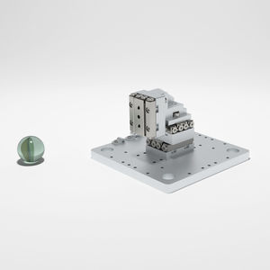
Stroke : 12 mm
... 36 (L x W x H) Center of vert. Stage above Ground [mm] - 25 (19 ... 31) Within the scope of SmarAct’s modular system, fully pre-built and pre-configured positioning systems are available. These pre-defined positioning ...
SmarAct GmbH
Stroke : 21 mm
... (L x W x H) Center of vert. Stage above Ground [mm] - 37 (26.5 ... 47.5) Within the scope of SmarAct’s modular system, fully pre-built and pre-configured positioning systems are available. These pre-defined positioning ...
SmarAct GmbH
Stroke : 26, 21 mm
... Based on two SLC-1740 stages for X and Y with 26 mm travel range and one SLC-1730 with 21 mm travel range for Z. The system is able to handle payloads of up to 1.5 N. Mechanical Stages used - SLC-1740 (X, Y); SLC-1730 ...
SmarAct GmbH
Stroke : 0.5 in
... Ball Slide Positioning Stage Family: 100 Model: 101-XY Price: $ 420.00 Add metric micrometer heads w/standard inch threaded holes $0.00 Add Posi-Lock carriage lock $108.00 ...
DELTRON
Stroke : 0.5 mm
... Side Drive Positioning Stage Family: 101SD, R101SD Model: 101SD- XYZ Price: $ 721.00 Add metric micrometer heads w/standard inch threaded holes $0.00 Add Posi-Lock carriage lock $163.00 ...
DELTRON
Stroke : 0.5 in
... Side Drive Positioning Stage Family: 101SD, R101SD Model: R101SD- XYZ Price: $ 927.00 Add metric micrometer heads w/standard inch threaded holes $0.00 Add Posi-Lock carriage lock $163.00 ...
DELTRON
Stroke : 50 mm - 1,000 mm
Speed: 200,000 mm/s
Repeatability: 0.5 µm - 1 µm
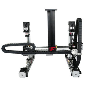
... Gantry style cartesian robots with large working areas. All moving axes located above work area. - XYZ Gantry 300 x 300 x 50 mm travel - Ball screw mechanism - Stepper or servo motor driven Options include: - larger ...

Stroke : 50 mm
Speed: 20, 10 mm/s
... testing, alignment and component assembly in any application on the factory floor or laboratory environments. The precision ball screw or micrometer grade lead screw provide excellent accuracy and repeatability with ultra-fine positioning ...
Stroke : 300 mm
... Low profile motorized actuators with precision ball screw provide exceptional accuracy, repeatability and ultra-fine positioning resolution capability to 1 micron in a very compact, low profile unit. They are ideal for space-critical ...
Stroke : 5 mm
Speed: 1 mm/s
Load: 25 g
... - for ultra-low temperatures up to 4K - for high vacuum conditions up to 10^(-9) mbar Miniature translation stages for ultra low temperatures with piezo electric inertial drive. UHV edition of the ML 17. Technical data Width - ...
mechOnics ag
Stroke : 5 mm
Speed: 1 mm/s
Load: 25 g
... ultra-low temperatures up to 4K very compact design for high vacuum conditions up to 10^(-6) mbar Miniature translation stages for ultra low temperatures with piezo electric inertial drive. Technical data Width - 17 mm Height ...
mechOnics ag
Stroke : 2 mm
Speed: 1.2 mm/s
Load: 46 g
... very compact design especially for optical devices and samples Miniature xyz positioners with piezo electrical inertial drive. Technical data Width - 35 mm Height - 18.5 mm Depth - 25 mm Max. Load (3 axis) Mx, My, Mz (momentum) ...
mechOnics ag
... SPIDER - POLYVALENT PALLETIZER • Maximum gripping surface • Reduced drive inertia • Ideal for handling, positioning and storing ...
Stroke : 3 mm
Load: 1 lb
... of dovetail stages integrates a coarse fast travel stage and a fine adjustable stage in one simple device. The coarse fast action is controlled by a 0.74-inch diameter knob that is attached to a multi-lead ...
Siskiyou
Stroke : 100 mm - 200 mm
Speed: 0 m/s - 0.1 m/s
... closed-loop linear stage, the X-LRM-DE, has hardened steel construction and recirculating ball bearing guides, which provide thermal stability and exceptional stiffness. The integrated linear encoder provides high accuracy positioning ...
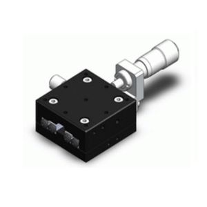
Stroke : 45, 10, 20 mm
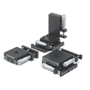
... found in the cable table. The motorized measurig stages MTM 60 are designed for applications where precision and very compact mechanical dimensions are primarily demanded. Combinations of XY or XYZ mountings with very ...
OWIS GmbH

Stroke : 20, 200 mm
Speed: 500, 30 mm/s
Repeatability: 0.3 µm
... Elevation Stage with Excellent Straightness and Flatness of Motion The vertical stage platform design provides excellent straightness and flatness, with better pitch and yaw performance compared to vertically mounted ...
NATSU PRECISION TRADE LIMITED
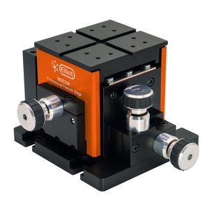
Stroke : 2 mm
Load: 4.5 kg
... resolution • Minimal arcuate displacement • Orthogonal alignment grooves • Ultra-stable patented† design XYZ flexure stage The MDE120 flexure stage is fitted with standard manual ...
Elliot Scientific

Jiangxi Liansheng Technology Co., Ltd.
Stroke : 6 mm - 200 mm
... Details : Precision Linear Translation Stages with Good Performance at an Economical Price Index 1.Features 2.Comparision Table of Linear Translation Stage Models 3.Catalog1 of Linear Translation Stages, ...
MPositioning Co., Ltd.
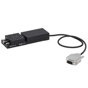
Stroke : 25 mm
... Thorlabs' wide selection of translation stages includes these 25 mm (1") travel translation stages. One-, two-, or three-axis stages are available. Both manual and automated actuator options exist. ...
Thorlabs

Stroke : 50 mm - 720 mm
Speed: 5 mm/s - 1,400 mm/s
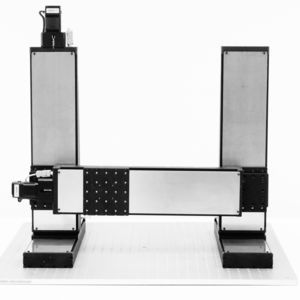
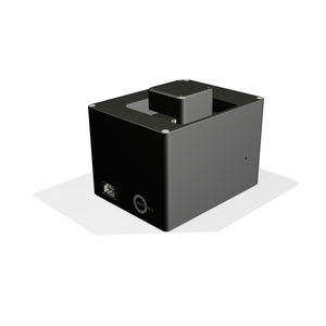
... This inspection system (shown here without cover) is specially designed for automated quality assurance. The positioning system allows positioning along two linear axes. A high-resolution camera or sensor is moved relative ...
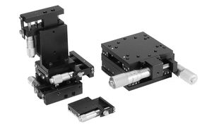
Stroke : 50, 20 mm
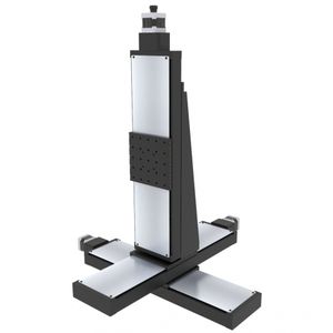
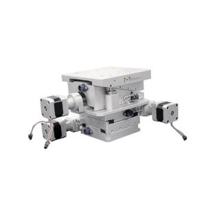
... Medical science XYZ- stage Precision ball screw driven Travel 50 x 50 x 20 mm Compact design ...
PM B.V.
the best suppliers