

- Metrology - Laboratory
- Metrology and Test Equipment
- Impedance tester
- Wuhan UHV Power Technology Co.,Ltd.


- Products
- Catalogs
- News & Trends
- Exhibitions
Capacitance tester UHV-321powerphase sequenceimpedance


Add to favorites
Compare this product
Characteristics
- Test type
- power, capacitance, phase sequence, impedance, short-circuit current
- Tested product
- for transformers, for single- and 3-phase equipment
- Applications
- for power systems, for production, for substations
- Configuration
- portable
- Other characteristics
- automatic, with LCD screen, with phase sequence indicator
Description
Introduction to Transformer Capacity Tester
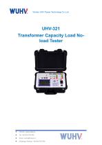
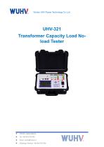
UHV-321 Transformer Capacity Load No Load Tester is a portable tester designed for measuring transformer capacity, no-load characteristics and short-circuit losses on distribution transformers.
Main Functions & Features of Transformer Capacity Tester
Applications / Typical Use of Transformer Capacity Load No Load Tester
Troubleshooting — common issues
Quality Assurance & Service of Transformer Capacity Tester
Technical Specifications
Precautions of Transformer Capacity Load No Load Tester
UHV-321 Transformer Capacity Load No Load Tester is a portable tester designed for measuring transformer capacity, no-load characteristics and short-circuit losses on distribution transformers.
Main Functions & Features of Transformer Capacity Tester
- Capacity measurement for distribution transformers (30kVA–31500kVA).
- No-load loss and short-circuit loss testing.
- Harmonic analysis with original waveform and bar-graph display to assess multiple harmonics and total harmonic distortion (THD).
- Automatic three-phase wiring verification with three-phase current-voltage vector diagram for three-phase tests.
- Multiple correction mechanisms: waveform correction, temperature correction, non-rated voltage/current correction and calibration correction to improve on-site accuracy.
- Automatic range switching for current and voltage measurements (0–100A; line voltage 0–750V / phase voltage 0–450V).
Applications / Typical Use of Transformer Capacity Load No Load Tester
- Field testing and acceptance of distribution transformers: capacity verification, no-load and short-circuit loss analysis.
- On-site power quality assessment through harmonic content analysis.
- Suitable for utility maintenance teams, commissioning and factory tests where correction functions and auto-ranging are required.
Troubleshooting — common issues
- No display on boot: check the AC 220V fuse box and replace the fuse if necessary.
- Screen goes black: press the reset button and restart the instrument.
- Incorrect measurement or calculation results: verify external wiring, check for manual operation errors or incorrect wiring selection, and confirm configured parameters.
- Voltage or current display reads zero: check whether the current-range fuse is blown.
Quality Assurance & Service of Transformer Capacity Tester
- Limited warranty and maintenance service provided by the manufacturer.
- Free maintenance during the warranty period; maintenance fees apply outside the warranty period.
- Refer to product documentation for warranty duration and contact details.
Technical Specifications
- Capacity measuring range: 30kVA ~ 31500kVA
- Current measuring range: 0 - 100A (auto-switching)
- Current measurement accuracy: ±(0.2% + 3 digits)
- Voltage measuring range: line voltage 0 - 750V; phase voltage 0 - 450V (auto-switching)
- Voltage measurement accuracy: ±(0.2% + 3 digits)
- Insulation resistance: > 100 MΩ
- Leakage current: < 3.5 mA
- Dielectric strength: power connection on chassis withstands 1500V; external transformer can extend measurement scope
- Frequency range: 40 ~ 65 Hz (accuracy class 0.2)
- Power input: AC 220V ± 10%
Precautions of Transformer Capacity Load No Load Tester
- 1. During the measurement process, be sure not to touch the metal parts of the test line to avoid injury.
- 2. When measuring wiring, it is necessary to strictly follow the instructions, otherwise the consequences will be borne by oneself.
- 3. Before testing, it is necessary to carefully check whether the set parameters are correct.
- 4. Use power sockets with grounding wires.
- 5. Cannot operate under excessive voltage and current limits.
- 6. During the short-circuit test, the short-circuit on the non pressurized side must be in good condition, otherwise it will affect the test results.
- 7. When conducting a short-circuit test, if a ring current transformer is installed in the high-voltage or medium voltage side outlet bushing, the secondary of the current transformer must be short circuited before the test.
- 8. The test wiring work must be carried out with the tested circuit grounded to prevent induced voltage electric shock. All short circuits, grounding, and leads should have sufficient cross-sectional area and must be securely connected. The testing organization work should be rigorous and communication should be smooth to ensure the safe and smooth progress of the testing work.
- 9. If the instrument is not used for a long time (more than three months), the battery will be depleted and damaged. Therefore, the instrument should be charged every three months (after turning on, the displayed battery level is about 90%) to ensure that the instrument can be used normally. The charging steps are as follows: plug in a 220V power supply, turn on the power switch, and the charging indicator light will turn on (this charging is in fast charging mode, and after charging for about two hours, the battery level will be displayed as 90% when turned on)
VIDEO
Other Wuhan UHV Power Technology Co.,Ltd. products
Transformer Tester


Related Searches
- Measuring device
- Test stand
- Portable testing system
- Digital testing system
- Automatic testing system
- Automatic test stand
- Industrial testing system
- Automatic test equipment
- Voltage testing system
- Portable measuring device
- Benchtop testing system
- Industrial gauge
- Manual test kit
- Test set
- Industrial test rig
- Laboratory testing system
- Tester with LCD screen
- Installation tester
- Portable test kit
- Industrial test equipment
*Prices are pre-tax. They exclude delivery charges and customs duties and do not include additional charges for installation or activation options. Prices are indicative only and may vary by country, with changes to the cost of raw materials and exchange rates.
About DirectIndustry
DirectIndustry is a marketplace that offers B2B players a complete experience, from product sourcing to purchase. DirectIndustry is an entity of VirtualExpo Group.
Are you a buyer?
Are you a supplier?